
What it does
A block is a group of objects with a single definition that you can insert many times. When you edit the definition once, every copy changes.
| Command | Alias | Syntax | Meaning |
|---|---|---|---|
| BLOCK | B, BMAKE |
BLOCK <name> [baseX baseY] |
Creates a block definition from the selected objects and replaces them with one block reference. The default base point is the lower-left corner. |
| INSERT | I |
INSERT <name> [x y] [scale] [angle] |
Inserts a block that exists in the drawing. If you give no name, the Content Browser opens. |
| BLOCKLIST | BL |
– | Lists the blocks in the drawing, their dynamic parameters and how many times each is used. |
| WBLOCK | W |
– | Writes the selected objects to a new DXF file. |
Where to find it
- Ribbon: Draw › Block › Block ▾ (Insert Block, Picture / Logo, Block Editor) and Insert › Blocks & Media
Steps
- Select the objects to turn into a block.
- Type
BLOCK TARGET 0 0and press Enter (name TARGET, base point 0,0). - Insert more copies:
INSERT TARGET 50 0andINSERT TARGET 100 0 1.5 45(scale 1.5, rotated 45°). - Check with
BLOCKLIST. The result isTARGET: static, no parameters [3 inserted].
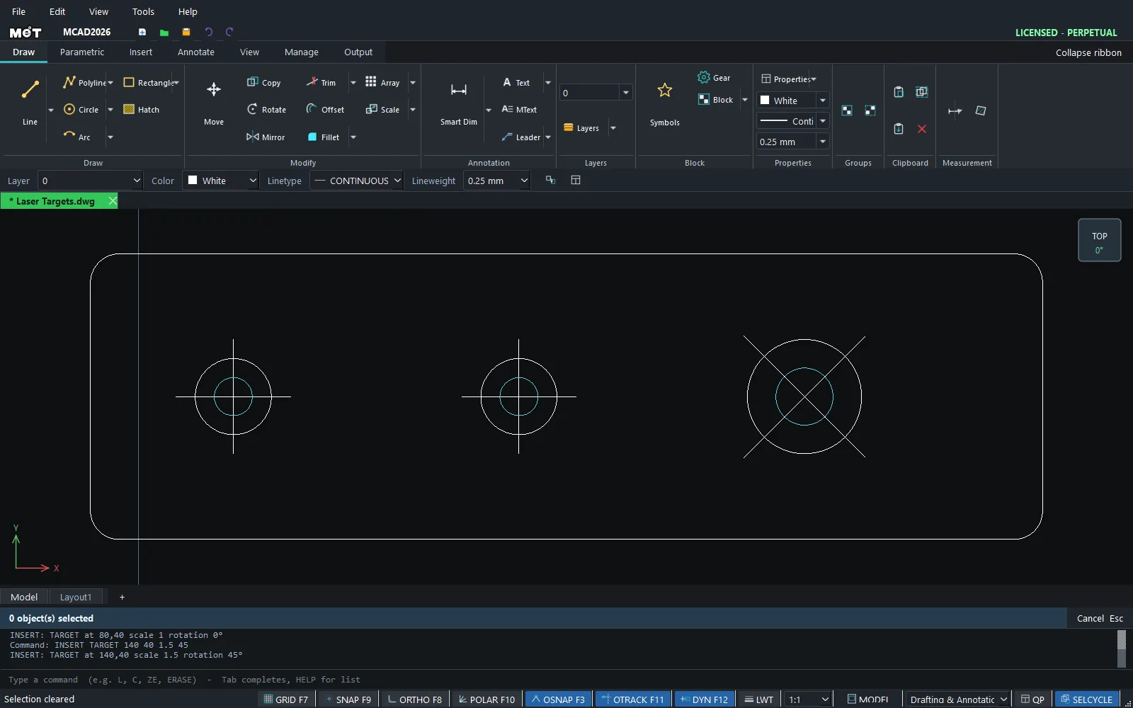
Note: GROUP only keeps objects together, while BLOCK creates a reusable definition. In a block from an opened DWG/DXF file, one click selects the whole block, and you can break it apart with EXPLODE.
Try it: Wall sockets around a workshop
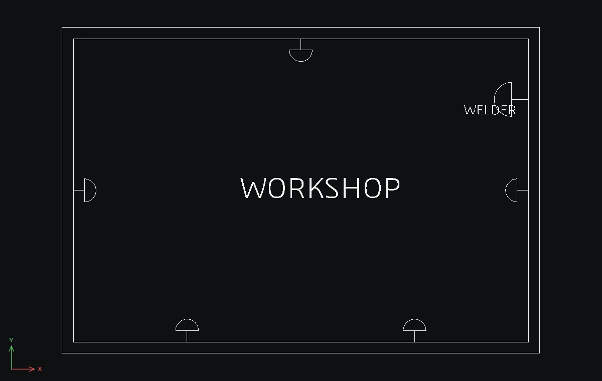
A 6 x 4 m workshop plan with power outlets on every wall. Draw the socket symbol once, make it a block, then INSERT places each socket with the right position and rotation.
- Socket symbol at the origin:
A(3-point arc) through-150,150,0,300,150,150; thenL-150,150→150,150andL0,0→0,150. - Select the three objects and type
BLOCK SOCKET 0 0. The point0,0, where the symbol touches the wall, becomes the insertion point. - Erase this first copy with
E. The definition stays in the drawing. - Walls:
REC0,0→6000Tab4000, thenREC-150,-150→6300Tab4300. - Sockets:
INSERT SOCKET 1500 0,INSERT SOCKET 4500 0,INSERT SOCKET 3000 4000 1 180,INSERT SOCKET 0 2000 1 -90,INSERT SOCKET 6000 2000 1 90. - A bigger outlet for the welder:
INSERT SOCKET 6000 3200 1.5 90.BLOCKLISTreportsSOCKET: static, no parameters [6 inserted].
Challenge: Open the definition with BEDIT, add two short earth-pin lines, BSAVE, and all six sockets change together.