
What it does
MCAD 2026 includes 240 electrical symbols drawn by MET to IEC 60617: contacts, push buttons, breakers, contactors, relays, motors, drives, sensors, PLC modules, terminals and more. Use them to draw control circuits, power circuits and panel layouts. Each symbol is drawn vertically on a 2.5 mm grid, and its insertion point is pin 1 (the top pin).
Where to find it
- Ribbon: Insert › Electrical › Symbols Library
- Content Browser palette › Group =
electrical
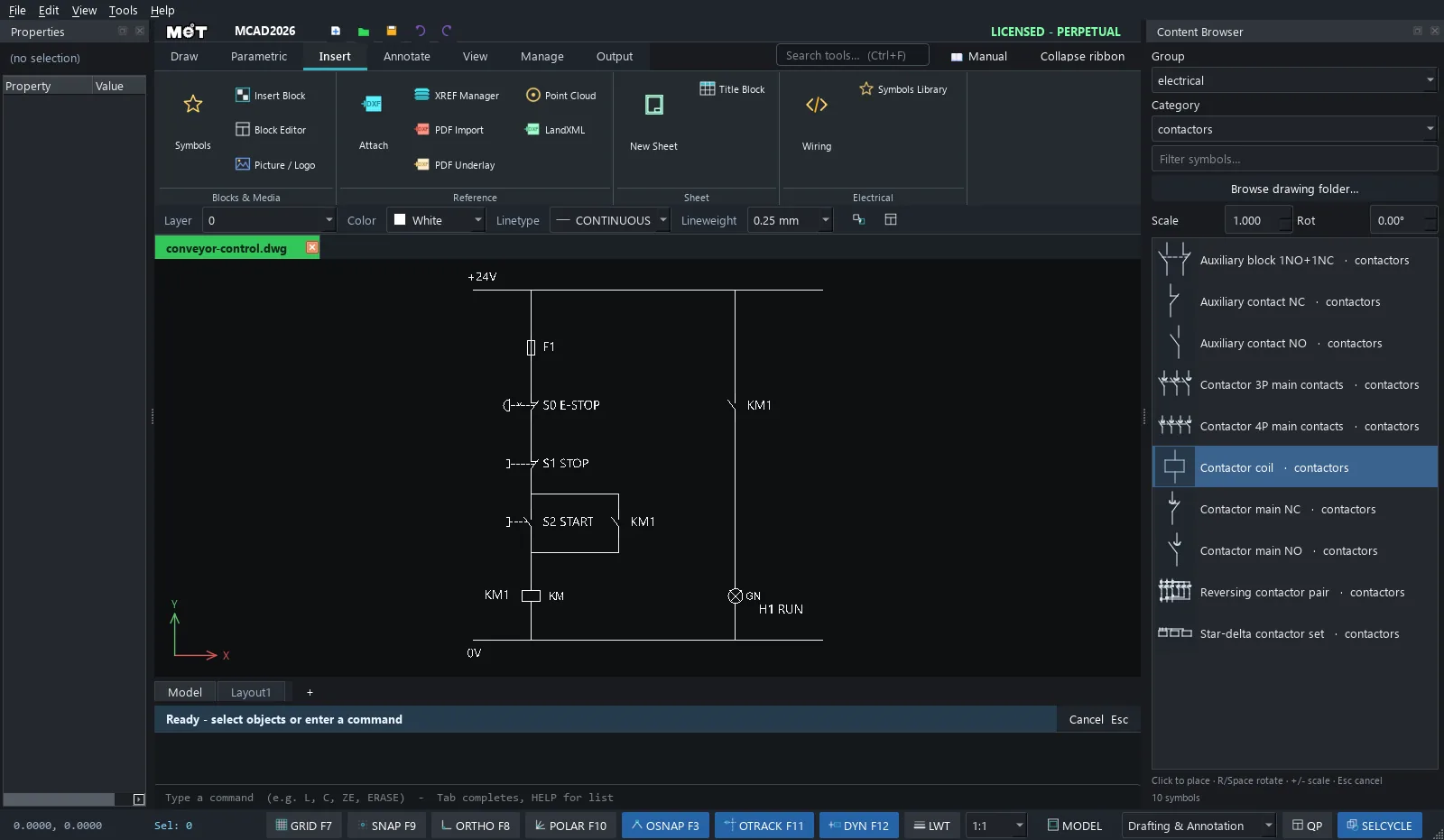
Categories in the electrical group
actuators, contactors, drives, earthing, indication, motors, outlets, passive, plc, power supply, protection, push buttons, relays & timers, sensors, switching, terminals, wiring (17 categories)
The same Content Browser also has the pneumatic group (ISO 1219 valves, cylinders, air treatment and vacuum) for the pneumatic side of a machine.
Steps
- Open Insert › Electrical › Symbols Library.
- Set Group =
electricaland Category =switching(or type a name in the Filter box, for examplepush button). - Click a symbol, then click a position on the drawing. Press
Rto rotate it 90° before you place it. - Turn on grid snap (
SNAP 5) to keep the terminals in line with the wires. - Draw the wires with
LINEorPLINE(turn on Ortho withF8).
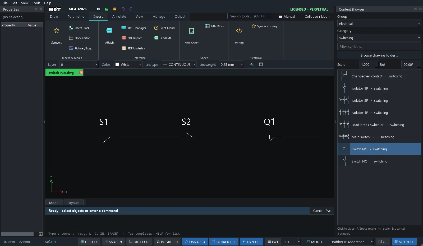
Note: To make your own symbol, draw it and run
BLOCK <name>. Add a tag withATTDEF, or keep the DXF file in a folder and use Browse drawing folder....
Try it: Conveyor start/stop circuit with E-stop
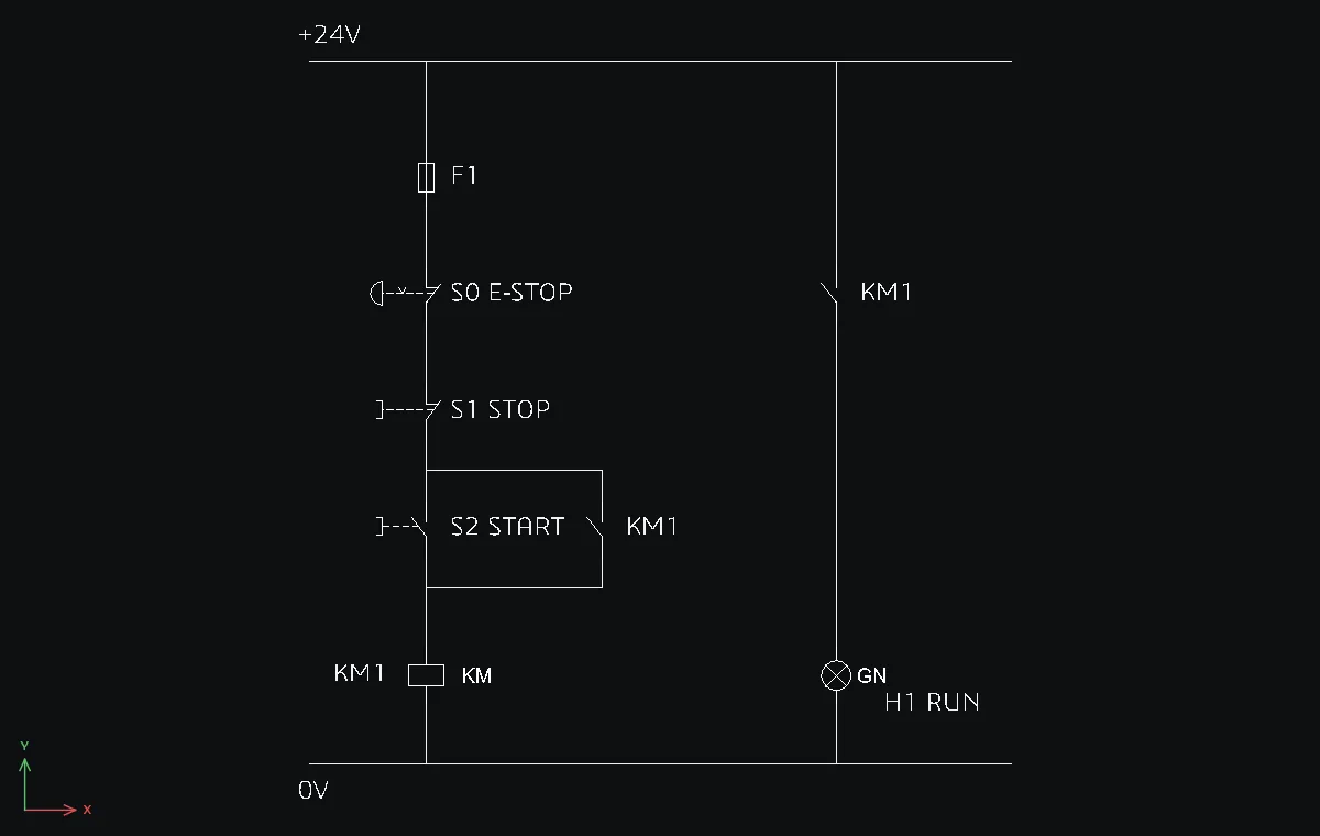
The classic control circuit of a belt conveyor: fuse, E-stop, stop and start buttons, a contactor coil that holds itself in, and a green RUN lamp. It is drawn the IEC way, with vertical current paths between a +24V rail at the top and a 0V rail at the bottom, so every symbol goes in upright with Rot 0.
- Type
SNAP 5and pressF8for Ortho. - Rails:
L0,120→120,120(+24V) andL0,0→120,0(0V). - Current path 1 at X 20, from the top: Category
protection› Fuse at20,105; Categorypush buttons› Emergency stop at20,85, Push button NC at20,65(Stop) and Push button NO at20,45(Start); Categorycontactors› Contactor coil at20,20. Each symbol is 10 long, so its bottom pin is 10 below the point you click. - Hold-in contact: Category
contactors› Auxiliary contact NO at50,45. Wire it in parallel with the Start button:L20,50→50,50→50,45andL50,35→50,30→20,30. - Current path 2 at X 90: Auxiliary contact NO at
90,85(the KM1 contact) and Categoryindication› Pilot lamp GN at90,20. - Join the symbols with
L, snapping to the pins:20,120→20,105,20,95→20,85,20,75→20,65,20,55→20,45,20,35→20,20,20,10→20,0, and90,120→90,85,90,75→90,20,90,10→90,0. - Labels with
DT, Text height3:F1,S0 E-STOP,S1 STOPandS2 STARTto the right of each symbol,KM1at the coil and at both contacts,H1 RUNunder the lamp, and+24Vand0Von the rails. The coil and the lamp already showKMandGNinside the symbol.
Challenge: Lengthen the rails and add a third current path at X 120 with Category protection › Overload NO 97-98 and Category indication › Pilot lamp RD as a red fault lamp. Number the wires afterwards with TCOUNT.