
What it does
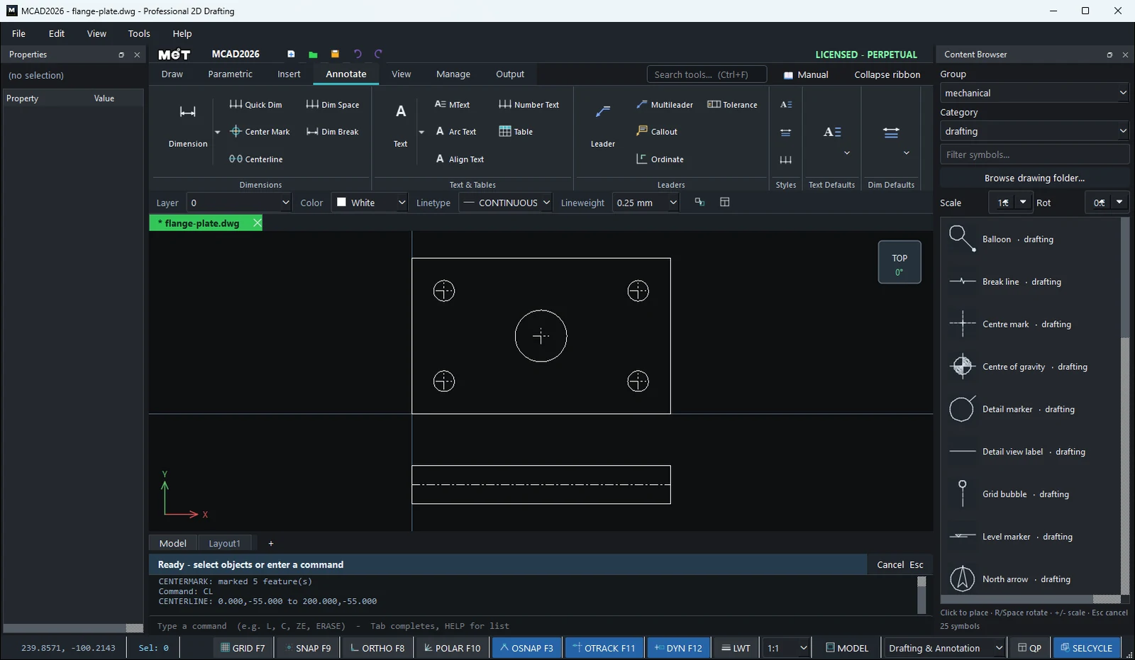
- CENTERMARK – draws a cross in the CENTER linetype at the centre of the selected circles or arcs.
- CENTERLINE – draws a CENTER line midway between two lines. For parallel lines you get the middle line. For lines that converge you get the angle bisector.
Where to find it
- Ribbon: Annotate › Dimensions › Center Mark / Centerline or Draw (Center Mark submenu)
- Command line:
CENTERMARK(aliasesDIMCENTER,DCE) - Command line:
CENTERLINE(aliasCL)
Steps
- Select the circles (for example with
QSELECT circle). - Type
CENTERMARKand press Enter (orCENTERMARK 5to set the arm length to 5). - For CENTERLINE: select two lines, then type
CL.
| Option | Meaning |
|---|---|
CENTERMARK [size] |
The arm length. If you omit it, 25% of the radius is used. |
Try it: DN50 pipe flange
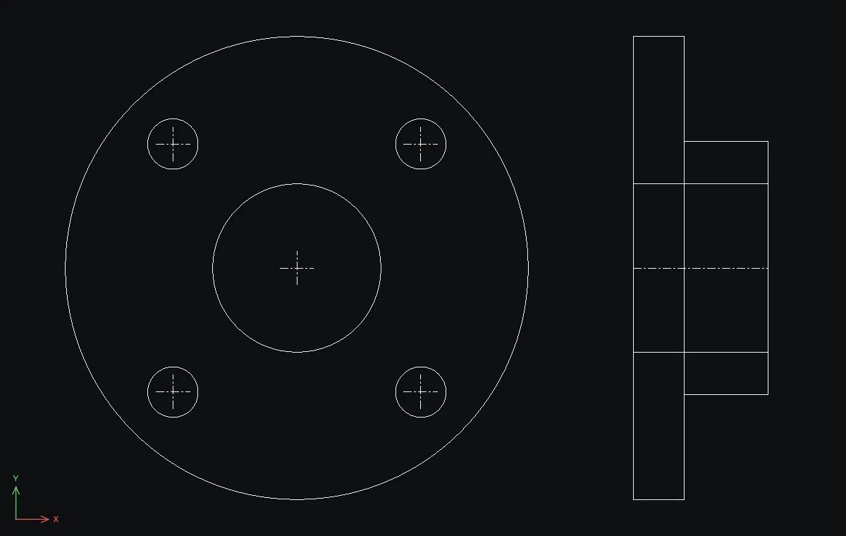
A standard DN50 pipe flange: Ø165 outside, Ø60 bore and four Ø18 bolt holes on a 125 mm pitch circle, in a front view and a side view. Two commands add every centre line.
- Front view:
C0,0radius82.5, thenC0,0radius30for the bore. - One bolt hole:
C44.19,44.19radius9. Select it, typeARRAYPOLAR 4and click0,0as the centre. - Side view:
REC120,-82.5→18Tab165(flange),REC138,-45→30Tab90(hub), then the two bore linesL120,-30→168,-30andL120,30→168,30. - Select the six circles of the front view and type
CENTERMARK 6. Every hole and the bore get a 6 mm centre cross. - Select the two bore lines and type
CL. A CENTER line appears midway between them: the axis of the flange.
Challenge: Undo step 4 and run CENTERMARK with no number. The arms become 25% of each radius, so the bolt holes get 2.25 mm arms and the bore 7.5 mm.