
What it does
TOLERANCE creates a Geometric Tolerance (GD&T) frame from lines and text, so it exports to DXF and prints correctly in any program.
Where to find it
- Ribbon: Annotate › Leaders › Tolerance (shows the list of symbols)
- Command line:
TOLERANCE(AliasTOL)
Steps
- Type
TOLERANCE POSITION 0.05 A Band press Enter (symbol, value, datums...). TOLERANCE: click where the frame goesClick a location.
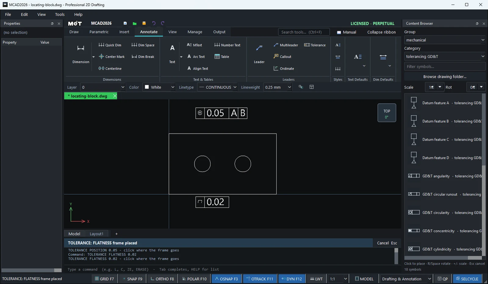
Supported symbols
| Keyword | Characteristic |
|---|---|
| STRAIGHTNESS | Straightness |
| FLATNESS | Flatness |
| CIRCULARITY | Circularity |
| CYLINDRICITY | Cylindricity |
| PROFILE / PROFILELINE | Profile of a surface / profile of a line |
| ANGULARITY | Angularity |
| PERPENDICULARITY | Perpendicularity |
| PARALLELISM | Parallelism |
| POSITION | Position |
| CONCENTRICITY | Concentricity |
| SYMMETRY | Symmetry |
| RUNOUT / TOTALRUNOUT | Runout / total runout |
TOLERANCE ? lists the symbols on the Command line. The text height follows the current text height setting.
Try it: GD&T on a motor shaft
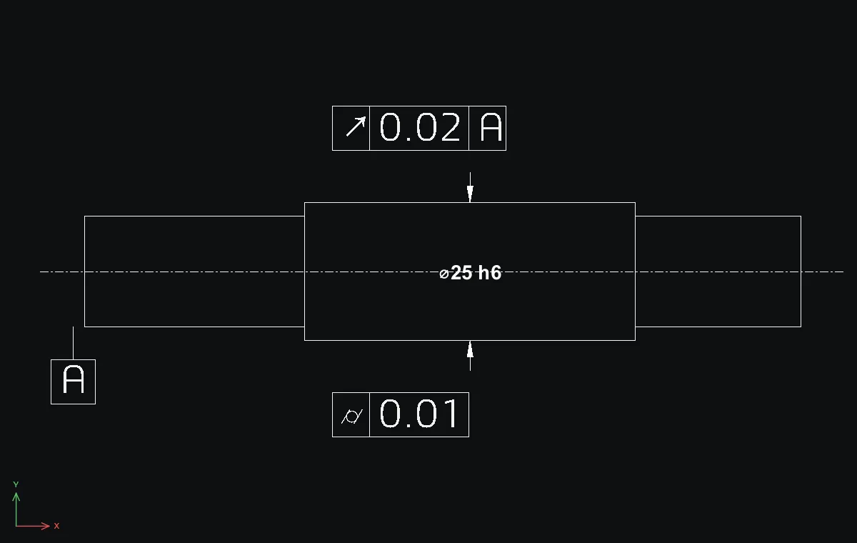
A stepped motor shaft whose middle Ø25 h6 section carries the bearing. Two feature control frames tell the inspector how round and how true that seat must be, measured against datum A.
- Shaft, left to right:
REC0,-10→40Tab20,REC40,-12.5→60Tab25(bearing seat),REC100,-10→30Tab20. Axis:L-8,0→138,0. - Bearing seat:
DVEfrom70,-12.5to70,12.5, placed on the shaft. ThenDIMPOST %%c<> h6andDIMOVERRIDE precision 0. It reads⌀25 h6. - Datum A:
REC-6,-24→8Tab8,DTwith Text height5and typeAinside the box, thenL-2,-16→-2,-10up to the shaft. TOLERANCE RUNOUT 0.02 A, then click above the seat at45,22.TOLERANCE CYLINDRICITY 0.01, then click below the seat at45,-30. Both frames use the text height 5 from step 3.
Challenge: Type TOLERANCE ? to list all symbols, then add TOLERANCE PERPENDICULARITY 0.03 A for the shoulder at X 40.