
What it does
DIMORDINATE shows the X or Y coordinate of a point (for example, the centre of a hole) relative to the origin. It is often used on plates with many holes.
Where to find it
- Ribbon: Draw › Annotation › Leader ▾ › Ordinate or Annotate › Leaders › Ordinate
- Command line:
DIMORDINATE(aliasDOR)
Steps
- If needed, move the origin to the corner of the part with
UCS ORIGIN x,y. - Type
DORand press Enter. - Click the point you want to dimension.
- Drag down or up, then click to show the X value. Drag left or right, then click to show the Y value.
- Repeat the command (press Enter) for the next point.
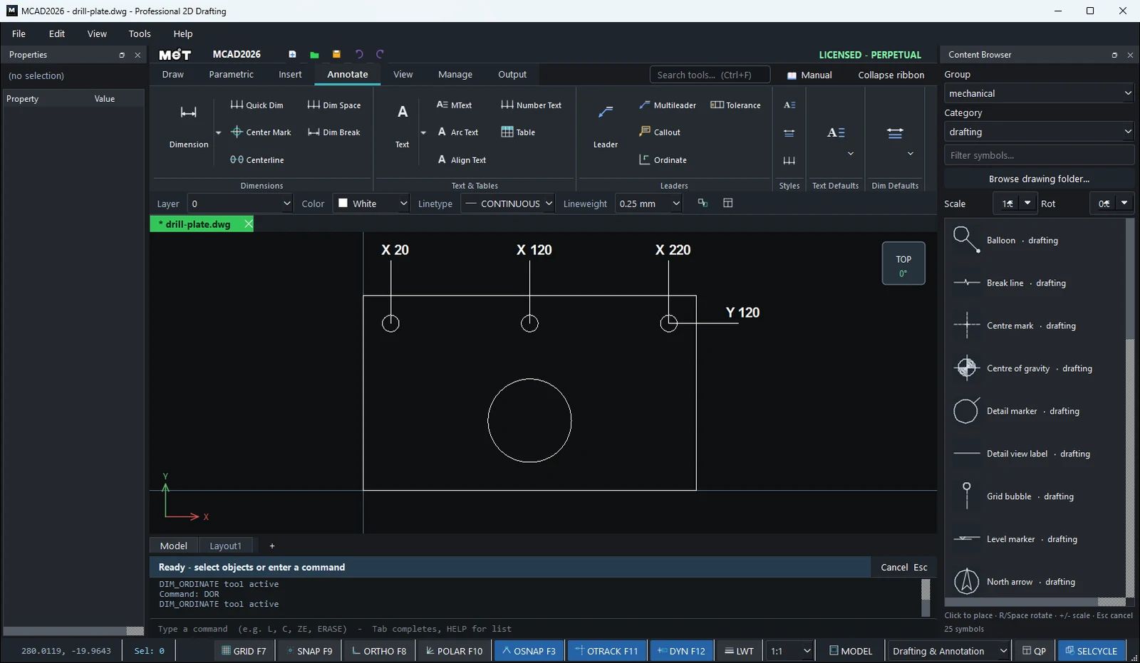
Try it: Push-button panel insert
A 220 x 80 insert plate for a control desk with five Ø22.5 holes for 22 mm push-buttons. Ordinate dimensions give every hole centre straight from the zero corner, which is how a CNC operator wants to read it.
- On Annotate › Dim Defaults, set Dim H
5and Arrow3so the numbers suit a part this size. REC0,0→220Tab80.- First hole:
C30,40radius11.25. Select it and typeARRAYRECT 5 40 0for holes at X 30, 70, 110, 150 and 190. DOR, click the corner0,0, drag down and click:X 0.00. Press Enter to repeat the command and do the same on the centre of each hole.DORon the centre of the last hole, drag to the right and click:Y 40.00. Do the same on the corner220,0:Y 0.00.
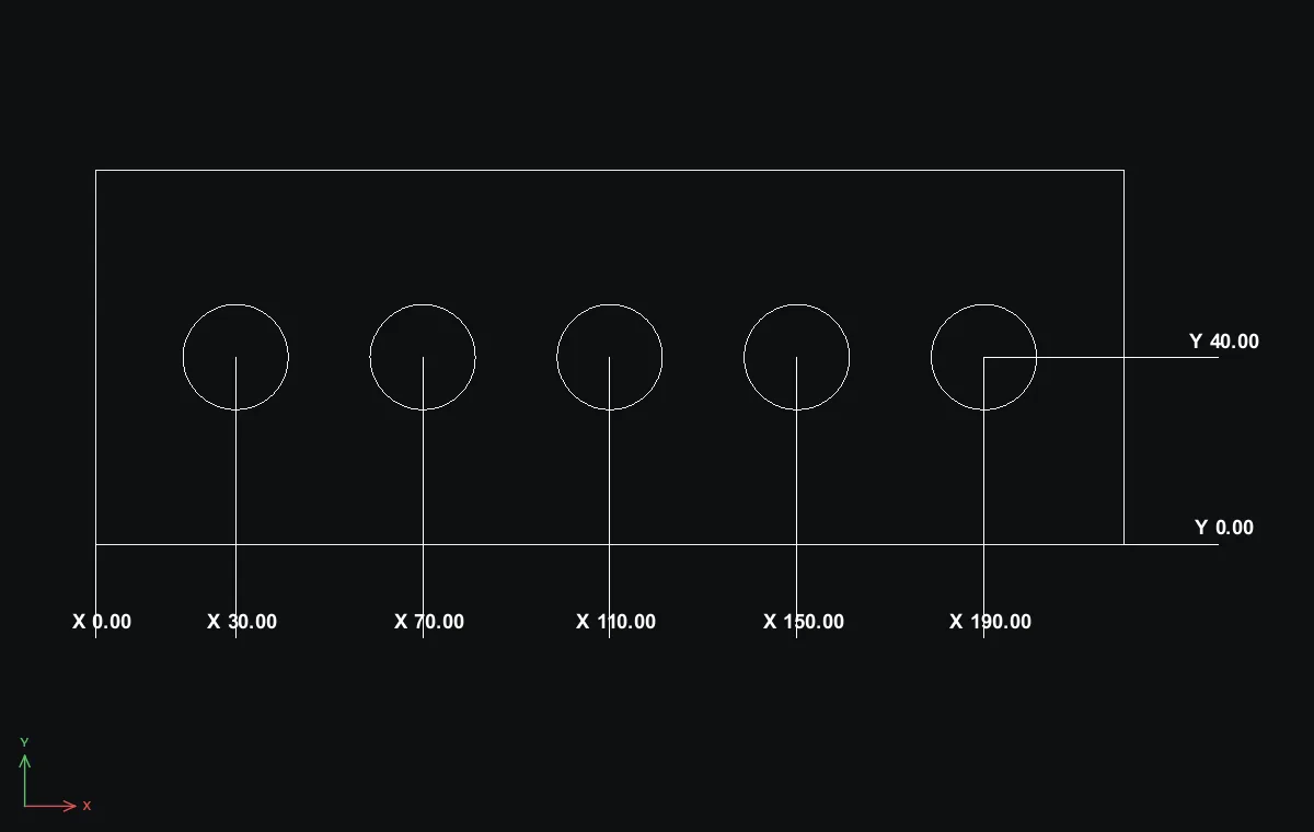
Challenge: Add two Ø5 fixing holes at 10,10 and 210,70 and give them X and Y ordinates as well.