
What it does
This tutorial walks you through drawing a bracket plate that is 240 x 140 mm, with a Ø50 centre hole and four Ø12 mounting holes in the corners. You add dimensions and save the file. It takes about 5 minutes.
Step 1: Turn on grid snap and draw the rectangle
- Type
SNAP 10and press Enter. This turns on grid snap at 10 mm, so your clicks land exactly on grid points. - Type
RECand press Enter (or use the Ribbon Draw › Draw › Rectangle). - Click the first corner at point 0,0.
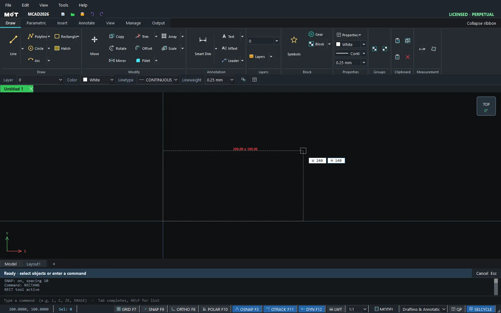
- Move the mouse to the upper right. The Smart Input box next to the cursor shows W and H.
- Type
240, pressTab, type140, then press Enter.
Step 2: Draw the holes
- Type
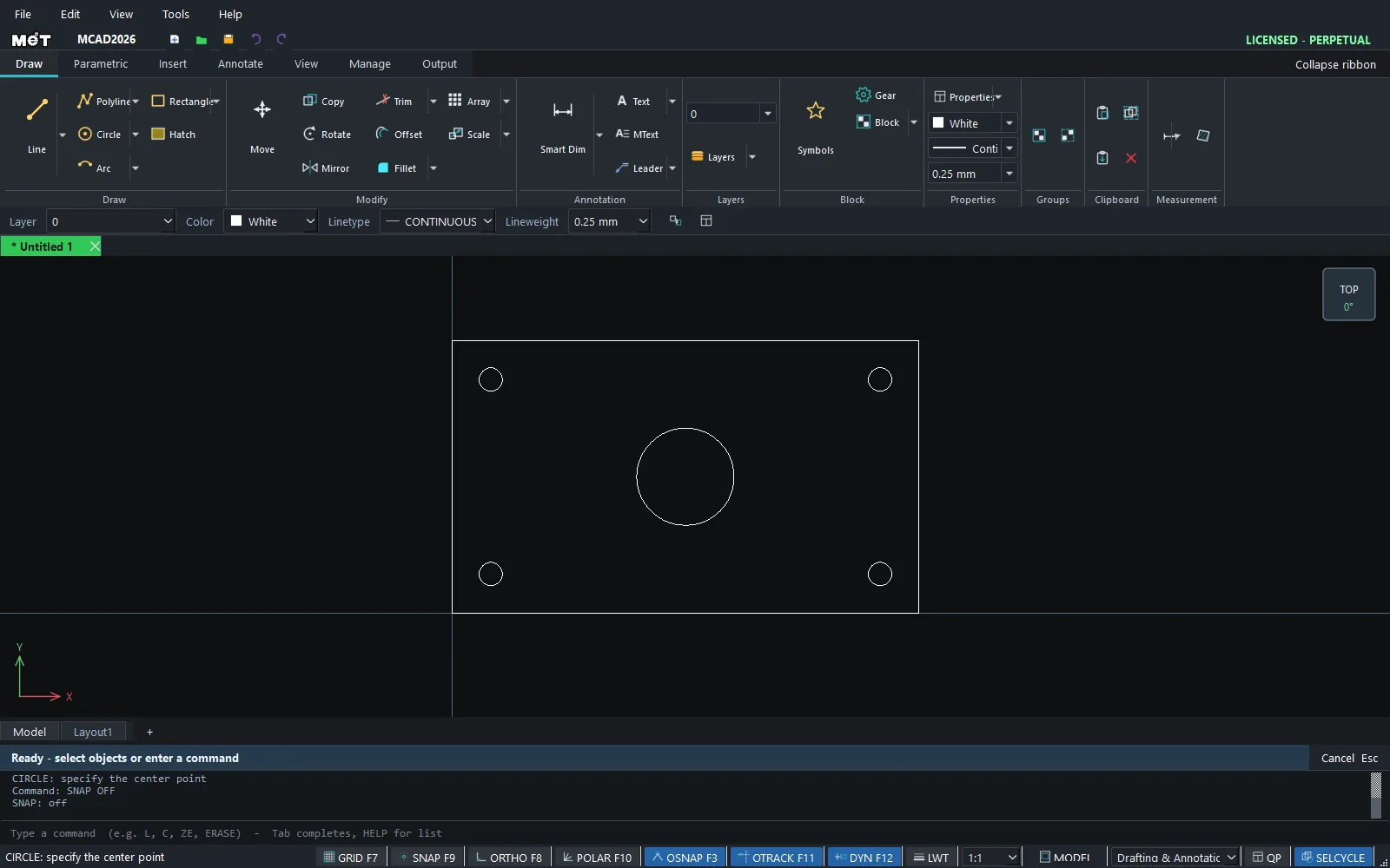
Cand press Enter. Click the centre point at 120,70. - Type the radius
25and press Enter. - Repeat for the 4 mounting holes at 20,20 / 220,20 / 20,120 / 220,120 with radius
6. - Type
SNAP OFFto turn off grid snap. Object Snap keeps working as usual.
Step 3: Add dimensions with Smart Dimension
- Type
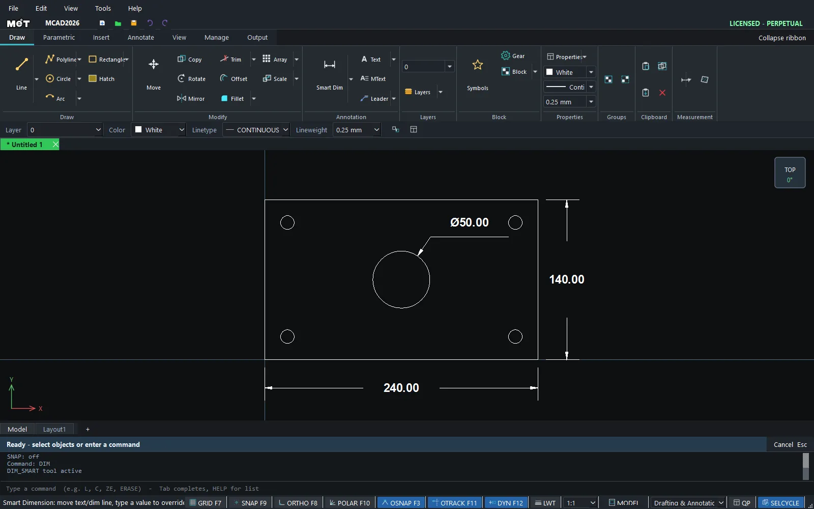
DIMand press Enter (or use the Ribbon Draw › Annotation › Smart Dim). - Click the bottom edge, then click an empty area below the part. A 240 dimension is attached to the mouse. Click again to place it.
- Click the right edge, click an empty area, then click to place it. This gives 140.
- Click the circumference of the centre hole. This gives Ø50. Move it into position and click.
- Press
Escto end the command.
Step 4: Save
- Press
Ctrl+S. The new drawing has no name yet, so the Save As dialog opens. - Choose the type
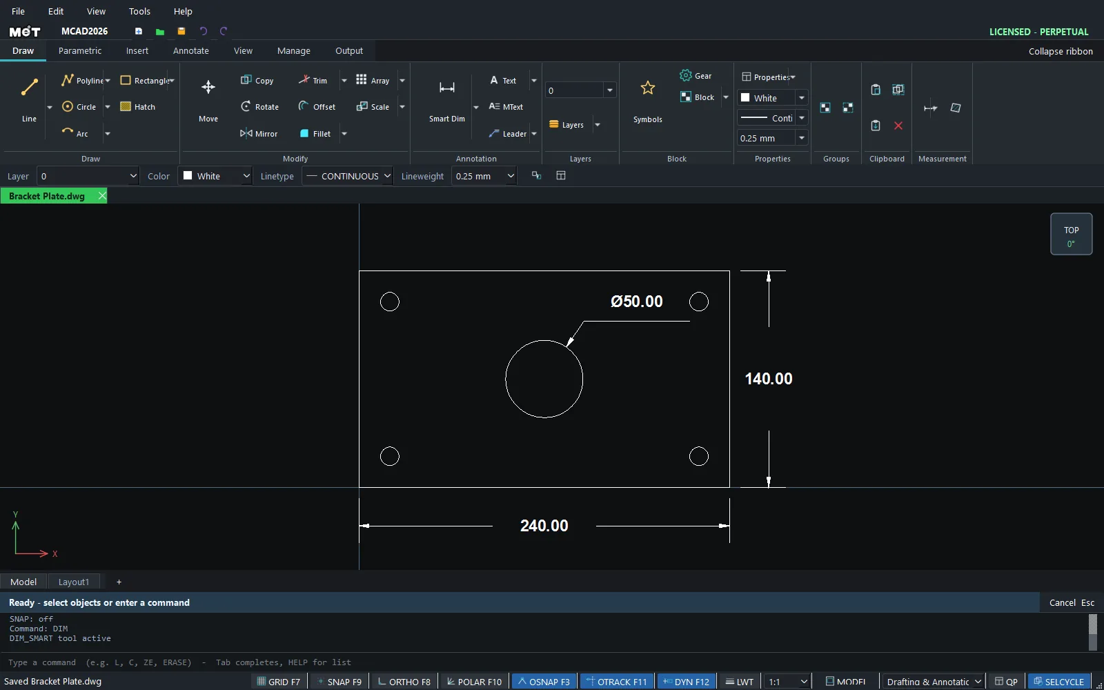
AutoCAD Drawing (*.dwg)orDXF (*.dxf), enter a name and click Save. - The tab at the top changes to the file name, and the Status bar shows
Saved ....
Note:
FILLETworks on LINE objects (and a LINE with an ARC or CIRCLE) only, not on an outline drawn withRECorPLINE. For R12 rounded corners, draw the rectangle as fourLINEs, thenFILLET. See FILLET and CHAMFER.
Try it: Your second drawing, a house-number plaque
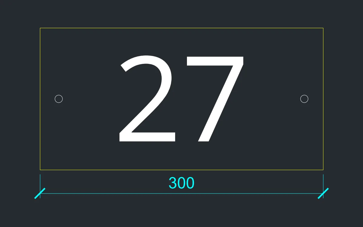
You have drawn the plate. Now make something for your front gate: a 300 x 150 mm house-number plaque with screw holes, ready to laser-cut from a DXF file.
Don't have the program yet? Download the installer from license.mechdesigned.com/download/MCAD or get it from the Microsoft Store.
REC0,0, then300Tab150Enter.- Screw holes:
C20,75radius4andC280,75radius4. - Type
TEXT, set the height to90, click in the middle of the plaque and type your number, for example27. - Press
Ctrl+S, chooseDXF (*.dxf)and name ithouse-number. It is ready for the laser shop.
Challenge: Redraw the plaque outline as four LINEs (FILLET does not work on a REC outline), then round all four corners with FILLET radius 15. See FILLET and CHAMFER.