
What it does
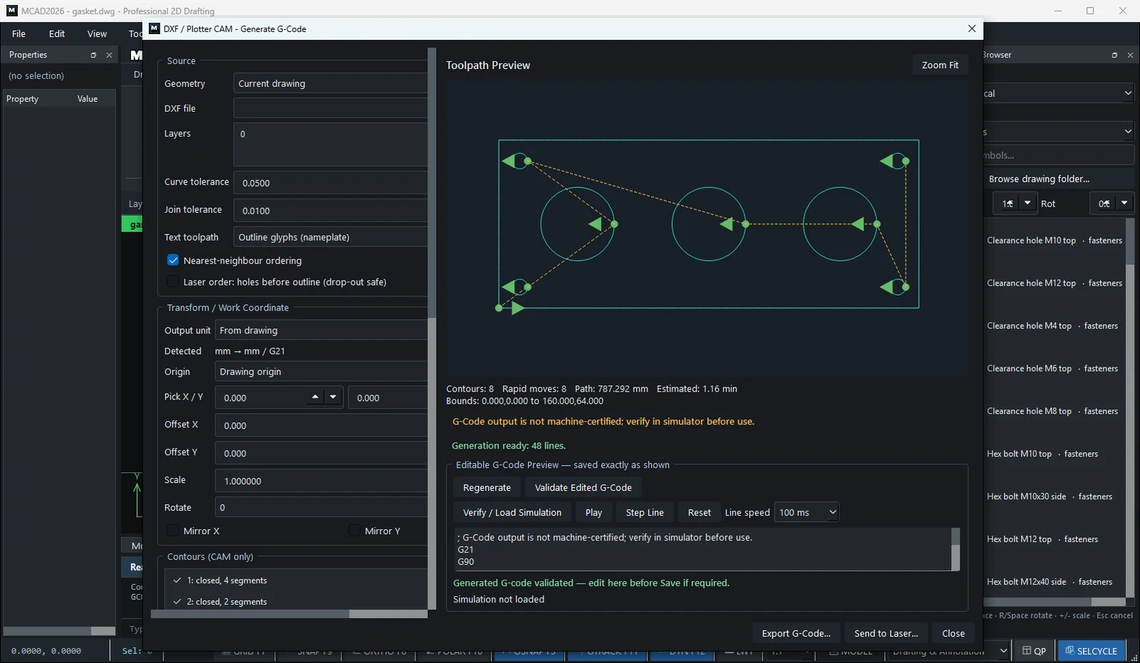
GCODE converts the lines in a drawing (or an external DXF file) into toolpaths and G-code. It shows a preview, lets you edit the G-code, and simulates the run before you export.
Where to find it
- Ribbon: Output › Interchange › Generate G-Code
- Command line:
GCODE(aliasesCAM,NCOUT) - Menu: File › Export › Generate G-Code...
Steps
- Draw or open the drawing (closed shapes for cutting).
- Click Generate G-Code. Choose Source › Geometry (Current drawing, Selected entities, Visible entities, Selected layers, External DXF file).
- Set Transform / Work Coordinate (Origin, Offset, Scale, Rotate, Mirror).
- Choose Machine / Post-processor › Profile, then enter Feed, Plunge, Rapid, Safe Z, Cut Z and Passes.
- Check the Toolpath Preview image and the summary of Contours / Path / Estimated time.
- Click Verify / Load Simulation, then Play or Step Line to simulate.
- Click Export G-Code... and save the file.
Main options
| Group | Options |
|---|---|
| Source | Geometry, DXF file, Layers, Curve tolerance, Join tolerance, Text toolpath (Outline glyphs / SHX strokes), Nearest-neighbour ordering, Laser order: holes before outline |
| Transform / Work Coordinate | Output unit (From drawing / mm / inch), Origin (Drawing origin / Lower-left / Center / Pick point), Offset X/Y, Scale, Rotate (0/90/180/270), Mirror X/Y |
| Contours (CAM only) | Reverse cut direction, Open / Close, Start Next |
| Machine / Post-processor | Profile (Generic CNC, GRBL Laser/Router, Laser / Plasma cutter and others), Feed rate, Plunge rate, Rapid rate, Safe Z / Pen up, Cut Z / Pen down, Passes, Pass depth, Enable spindle / laser, Power / RPM, Precision, Extension (.nc .gcode .tap .txt), G90 absolute, Preserve arcs as G2/G3, Line numbers, Work width/height, Header, Footer |
| Editable G-Code Preview | Edit the G-code directly. Regenerate / Validate Edited G-Code. |
Note: The G-code is not certified for your machine. Always check it with the simulator and make a test cut before real production. An orange warning message tells you which objects were skipped.
Try it: CNC-routed WORKSHOP sign
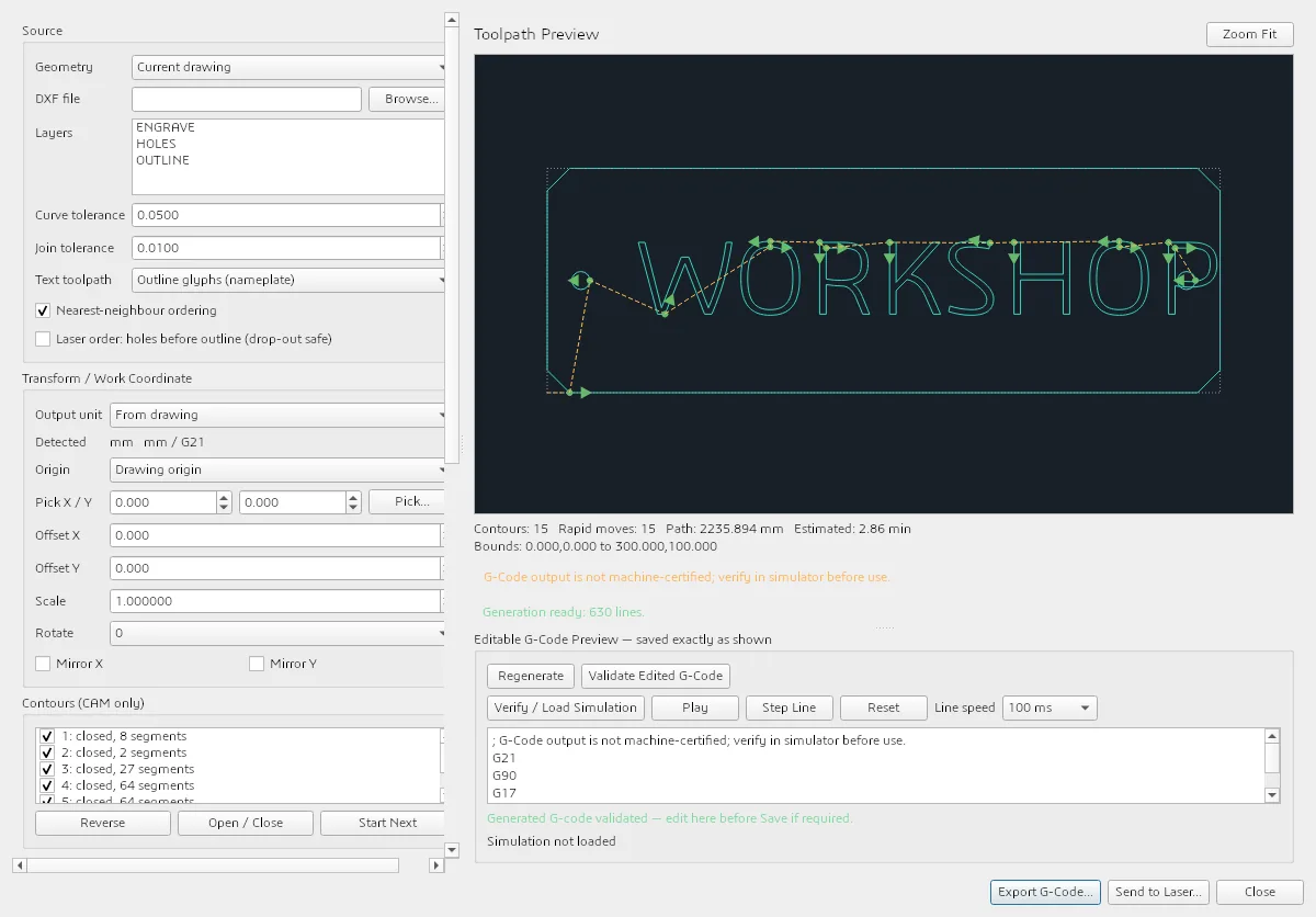
A 300 x 100 sign for the workshop door: chamfered corners, two fixing holes and the word WORKSHOP cut as letter outlines. GCODE turns all of it into one toolpath you can watch in the simulator before the router touches the board.
- Sign blank: Polyline - Closed Loop through
10,0290,0300,10300,90290,10010,1000,900,10, then Enter. - Fixing holes:
C15,50radius4andC285,50radius4. DTwith Text height32, typeWORKSHOPat about40,35.- Output › Interchange › Generate G-Code. Source: Geometry
Current drawing, Text toolpathOutline glyphs. - Machine / Post-processor: Profile
GRBL Laser/Router. The Toolpath Preview shows 15 contours: the outline, 2 holes and 12 letter contours (O, R and P each have an inside). - Click Verify / Load Simulation, then Play. When it looks right, Export G-Code... as
workshop_sign.gcode.
Challenge: Tick Laser order: holes before outline so the sign cannot drop out of the sheet before its holes and letters are cut.