
What it does
Operations for 3D curved surfaces such as moulds (a workpiece is required).
Where to find it
3D Milling › 3D Rough / 3D Finish / Tactics
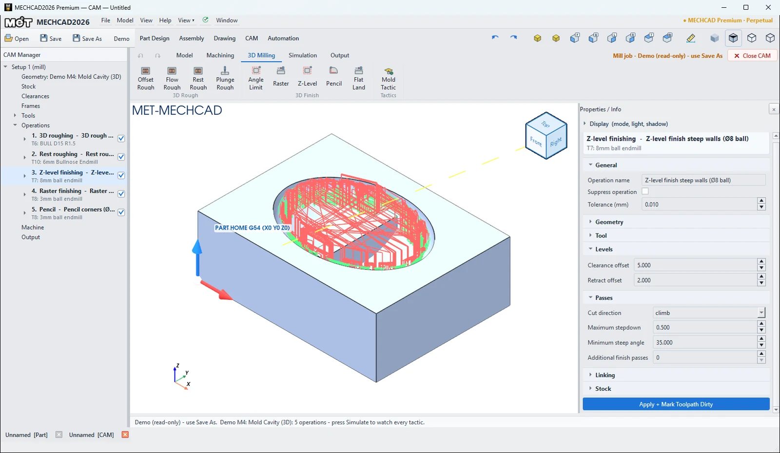
| Operation | Description | Defaults |
|---|---|---|
| Rough Offset 2D | Roughing with offset loops at constant Z levels. | stepdown 3, stepover 0.65×D, stock left 0.5 |
| Smooth Flow Rough | Raster-style roughing. | stepdown 1.5, stepover 0.5×D, stock left 0.5 |
| Rest Rough | Cuts only the material left by a reference operation (automatically references the previous operation). | stepdown 1, stock left 0.2 |
| Plunge Rough | Roughing by axial plunging. | pitch 6 mm (0 = automatic 0.8×D), stock left 0.5 |
| Angle Limiting | Mixed finishing: raster on shallow surfaces, Z-level on steep surfaces. | steep angle 40°, overlap 3° |
| Shallow Raster | Finishes shallow surfaces with a ball-nose cutter. | stepover 0.25 mm, maximum angle 40° |
| Steep Z-Level | Finishes steep surfaces with contour lines. | stepdown 0.25, minimum steep angle 35° |
| Pencil Cleanup | Cleans up concave corner grooves. | concavity 0.15 |
| Flat Land | Finishes flat floors with a flat-end cutter. | stepover 0.4, maximum angle 5° |
| Mold Tactic | Creates a set of 5 linked operations: 01 Rough Offset 2D, 02 Rest Rough, 03–04 Angle Limiting semi/finish, 05 Pencil. | – |
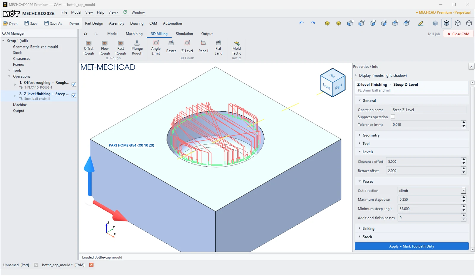
Note: 3D toolpaths are calculated when you Simulate or right-click › Show Toolpath (3-axis toolpath not calculated yet).
You can edit every operation in the Properties panel on the right when you click the operation in the CAM Manager. The panel sections are General, Geometry, Tool, Levels, Passes, Linking and Stock (see Operation Parameters for the meaning of each field).
Try it: Mould a bottle cap
Ever wondered how a bottle-cap mould is cut? This is a 60 × 60 × 25 insert with a Ø32 × 12 cap cavity, an R3 radius at the bottom and 24 grip ribs. One click on Mold Tactic builds the whole five-step strategy.
- Model a 60 × 60 block Extruded 25 mm. On the top face, draw a Ø32 circle at the centre and Extrude Cut it 12 mm. Fillet the bottom edge of the cavity R3.
- Sketch on the top face again: a Ø2 circle centred on the cavity edge (X 46, Y 30). Make a circular pattern of 24 copies around the centre and Extrude Cut them 8 mm. These are the grip ribs.
- CAM › New Job › Mill Template.
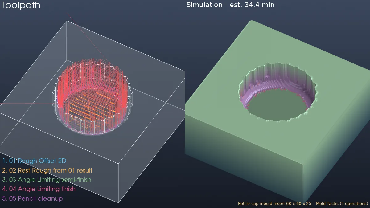
- Click 3D Milling › Tactics › Mold Tactic. Five operations appear: 01 Rough Offset 2D (T9, 10 mm), 02 Rest Rough from 01 (T1), 03 Angle Limiting semi-finish (T4, 6 mm ball), 04 Angle Limiting finish (T8, 3 mm ball) and 05 Pencil cleanup (T8).
- Click Simulate. The 3D toolpaths are calculated now (about 25 s on our test PC). The estimated time is about 34 min.
- Look at the ribs. The 3 mm ball cannot reach the bottom of the 2 mm grooves, so Solid Verify reports RESIDUAL there. Details this small need a smaller cutter or EDM.
Challenge: Add 3D Finish › Steep Z-Level and compare its finish on the cavity wall with 04 Angle Limiting finish.
Note: CAM is available only in MECHCAD Premium (and during the trial).