
What it does
Turns the view quickly to a standard direction. These buttons are on the top bar and work in every workbench.
Shared view buttons (top bar, right)

| Button | Meaning |
|---|---|
| Undo (Ctrl+Z) / Redo (Ctrl+Y) | Undo / redo |
| Zoom to fit | Zooms to show the whole part |
| Isometric view | 3D view (using the projection type you set) |
| Front, Back, Left, Right, Top, Bottom | Flat orthographic views |
| Measure | Measure tool. See Measure |
| View Display (4 buttons) | Shaded, Shaded + Edges, Hidden edges, Wireframe. See Display modes |
View Cube
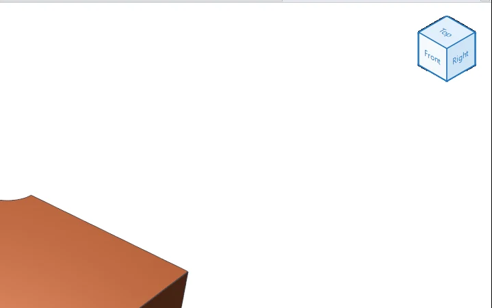
- Click a face of the cube › the flat view of that face (Top, Front, Right …)
- Drag the cube › rotates the view
- Right-click › Top, Bottom, Front, Back, Left, Right, Isometric and Hide View Cube
- You can show it again from View › View Cube
Normal To
- View › Normal To › XY / YZ / ZX or View ▾ › XY / YZ / ZX looks perpendicular to a main plane in orthographic view.
- In an assembly, right-click a component › View Normal to Face looks perpendicular to the face you click.
- Rot ↺ / Rot ↻ (View › Orientation) rotates the view 90° in the screen plane.
Orthographic / Perspective
View › Projection › Orthographic (no shrinking with distance) or Perspective (with depth). Your choice applies to every 3D view. You can set the default in System Options › Design Viewing.
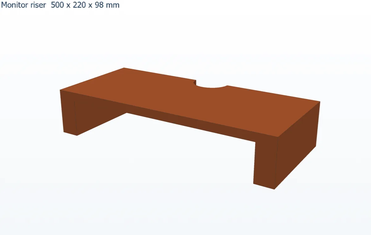
Try it: Monitor riser, checked from every side
A 500 mm riser that lifts your screen 98 mm and leaves room for a keyboard underneath. Use the standard views to check every size.
- Sketch on XY a rectangle 500 × 220 and Extrude 18 mm.
- Right-click the View Cube › Bottom. Right-click the bottom face › New Sketch on this face and draw two rectangles 40 × 220, one at each end. Finish Sketch and Extrude 80 mm (the legs grow downward from the face).
- Click Top. Sketch on the top face a circle Ø80 centred on the middle of the back edge, then cut it with Through All. This is the cable notch.
- Click Front: you see the legs and the 98 mm overall height. Click Right: the 220 mm depth.
- Click Isometric. Then use View › Normal To › XY and Rot ↻ to turn the top view 90° on the screen.
- Choose View › Projection › Perspective and back to Orthographic: in Front, the orthographic view keeps the legs the same height.
Challenge: Click a face of the View Cube instead of the buttons, then hide the cube with right-click › Hide View Cube and show it again from View › View Cube.