
What it does
The CAM tab creates toolpaths for 3-axis CNC mills and lathes from a part in Part Design or from a STEP/IGES/STL file. It simulates material removal with collision checking, then generates G-code and a setup sheet. Jobs are saved as .metcam.
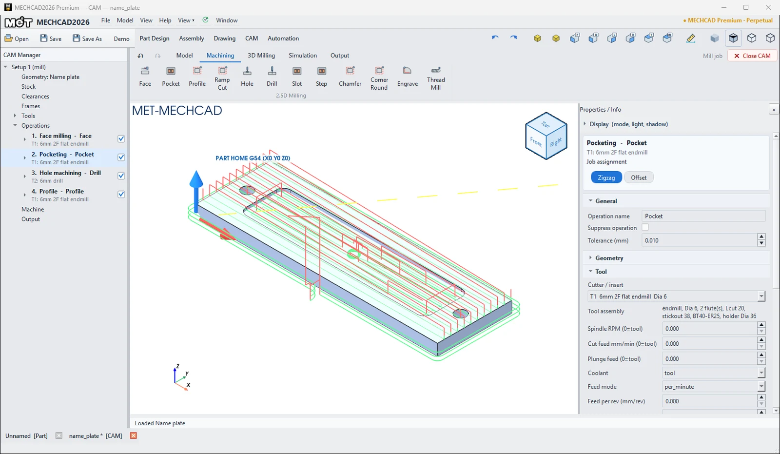
Parts of the window
| Part | Description |
|---|---|
| CAM Manager (left) | Setup 1 (mill/lathe): Geometry, Stock, Clearances, Frames, Tools, Operations, Machine, Output |
| Ribbon | Model, Machining, 3D Milling, Simulation, Output |
| Status badge (top right) | Mill job / Lathe job (sample jobs: Demo (read-only) - use Save As) |
| ✕ Close CAM | Closes the CAM job (asks to save) and clears the toolpaths |
| Properties (right) | Settings for whatever is selected in the CAM Manager |





Workflow
- New Job. Choose a Mill or Turn template.
- Check the Stock, Frame (WCS) and Clearances.
- Add tools from the Tool Library.
- Add operations: Face/Pocket, Profile, Drill, 3D, Turning.
- Simulate.
- Generate G-code and Shop PDF.
Note: A lathe job hides the 3D Milling tab and the 2.5D group. A mill job hides the Turning group. If the window is narrow, buttons that do not fit move into the » menu. CAM Undo/Redo use Ctrl+Z / Ctrl+Y.
Note: CAM is available only in MECHCAD Premium (and during the trial).
Try it: Mill a door name plate from start to finish
A 130 × 40 mm aluminium name plate with a recessed panel and two screw holes takes you through the whole CAM workflow, from model to G-code, in about ten minutes.
- In Part Design, sketch a 130 × 40 rectangle on XY starting at the origin and Extrude it 6 mm.
- Sketch on the top face: a 100 × 24 rectangle 15 mm from the left edge and 8 mm from the front edge, with R4 corners. Extrude Cut it 1.5 mm. Then add two Ø6 circles at X 7.5 and X 122.5 (Y 20) and Extrude Cut them Through All.
- Open the CAM tab › New Job › Mill Template › OK. The stock becomes 132 × 42 × 6.5 mm.
- Click Face, click the top face and press Enter.
- Click Pocket, click the floor of the recessed panel and press Enter. Top Z 6 and Floor Z 4.5 are read from the model.
- Click Drill, click both hole walls and press Enter. The T2 6 mm drill matches the holes.
- Click Profile, click a bottom outer edge of the plate and press Enter. In Properties › Levels, set Bottom / Floor Z to 0 so the plate is cut free.
- Click Simulate, then Play. The estimated time is about 6.8 min. Finish with Output › G-code and save
name_plate.nc(FANUC_MET 3Axis post, about 240 lines).
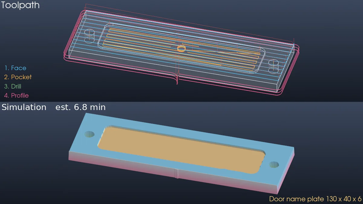
Challenge: Change the Face cutter to T3 12mm 3F face mill (Properties › Tool › Cutter / insert) and Simulate again. How much shorter is the estimated time?