
What it does
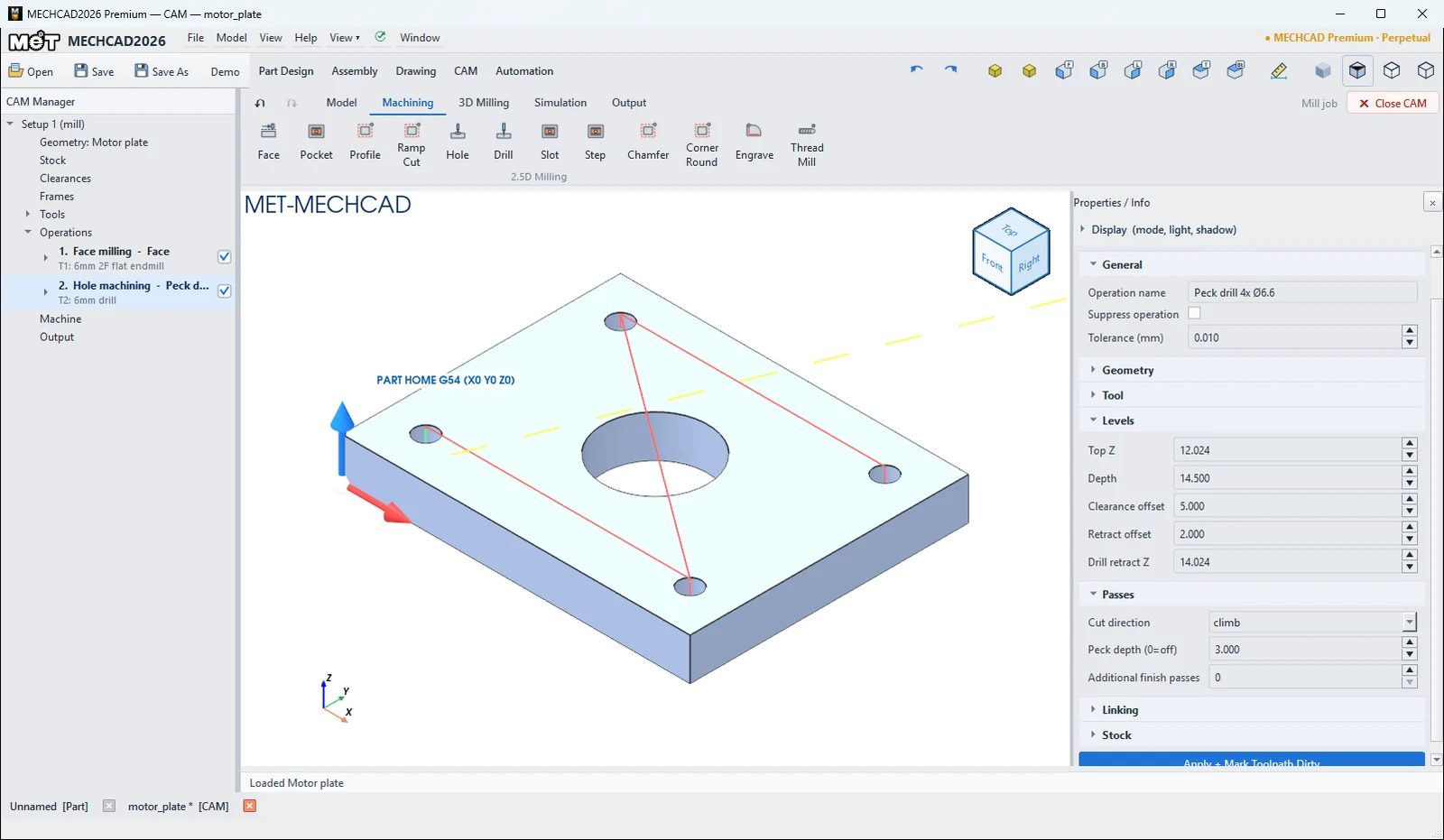
Drill, Hole, Peck Drill and Center drill the holes whose faces you select. All of them use Smart Hole: MECHCAD finds every hole in the faces you click, lists them in a table where you tick each hole, and chooses the drill for the hole size automatically. Enter a Peck depth to drill in steps.
Where to find it
Holes › Drilling › Center / Peck Drill / Drill / Hole
| Command | Settings applied |
|---|---|
| Drill / Hole | Peck depth 3 (3 mm per peck) |
| Peck Drill | Peck depth 1 |
| Center | Peck depth 0 (one pass), for spot / centre drills. After picking the holes, set a shallow Depth yourself. |
Steps
- Click Drill (or Hole, Peck Drill, Center).
- Click a flat face that has the holes in it (every hole whose rim lies on that face is found), or click the hole walls one by one (you can select several faces), then press Enter.
- In the Holes section of the operation box, tick only the holes you want to drill.
- Check the drill, Peck depth and Drill retract Z, then Simulate.
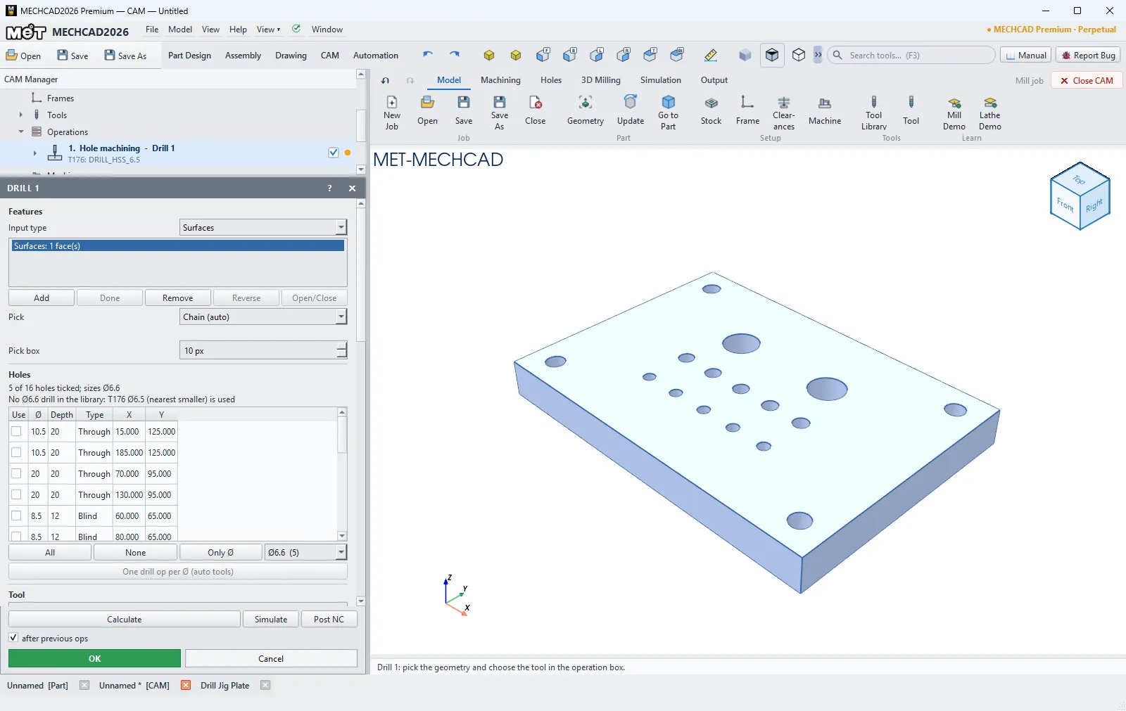
Smart Hole: the Holes table
| Item | Description |
|---|---|
| Use, Ø, Depth, Type, X, Y | One row per hole: the tick, the size, the hole depth, the type (Through or Blind) and the position |
| All / None | Ticks every hole / clears every tick |
| Only Ø + size box | Ticks only the holes of the chosen size (the box shows each size with its hole count, for example Ø6 (7)) |
| One drill op per Ø (auto tools) | When several sizes are ticked, makes one operation per size, each with the drill that fits. The original operation keeps the smallest size, and the names get the size added, for example Drill Ø8 |
| Summary line | For example 5 of 7 holes ticked; sizes Ø6 |
- Automatic drill: when one hole size is ticked, MECHCAD chooses a drill of exactly that diameter, from the job tools first and then from the library. If there is no exact size, it uses the nearest smaller drill and tells you so (it never picks a drill larger than the hole). A library drill is copied into the job.
- Depth: a blind hole is drilled to its bottom. A through hole is drilled the hole length + the drill point + 0.5 mm. Top Z is the top of the hole, and Drill retract Z = Top Z + 2.
- Holes you leave unticked never reach the NC. With no hole ticked you see Holes: tick at least one hole.
- When you pick the faces again, holes that are found again keep their tick.
Drill cycle settings
| Setting | Default | Description |
|---|---|---|
| Peck depth (0=off) | Per command (see the table above) | 0 = drill in one pass, > 0 = peck drilling (the Q value) |
| Drill cycle (NC) | auto | auto = G83 with a Peck depth, G82 with a Dwell, otherwise G81. You can choose g81 / g82 / g83 / g73, or expanded (written as G00/G01 moves) |
| Return plane | g98 | g98 = back to the initial level between holes, g99 = back to the R plane |
| Dwell (seconds) | 0 | Pause at the hole bottom (G82) |
| Drill retract Z | Top Z + 2 | R plane |
| Depth / Bottom Z | From the hole | Depth |
The default Fanuc mill post writes all the holes of an operation as one canned cycle, for example G17 G98 G83 X.. Y.. Z.. R.. Q3 F.., then the X / Y of each further hole, closed with G80. Other posts write G00/G01 moves.
Note: There is no tapping cycle yet. Use Thread Mill to cut internal threads by milling.
Double-click an operation in the CAM Manager to open its operation box, where you can edit every value. Its Parameters section has the General, Geometry, Tool, Levels, Passes, Linking and Stock pages (see Operation Parameters for the meaning of each field).
Try it: Drill a drill-jig plate
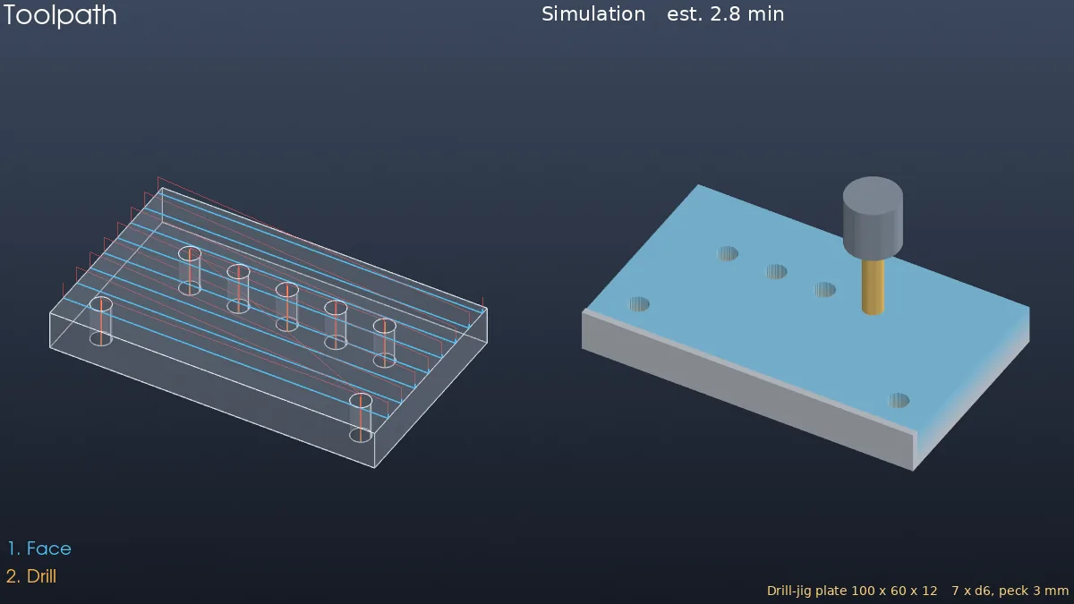
A drill jig puts every hole in a batch in exactly the same place. This 100 × 60 × 12 plate has five guide holes 15 mm apart and two dowel holes: one Drill operation, seven holes, peck drilling.
- Model a 100 × 60 × 12 plate. Draw seven Ø6 circles: five at Y 40 (X 20, 35, 50, 65, 80) and two at (10, 10) and (90, 10). Extrude Cut them Through All.
- CAM › New Job › Mill Template. In Stock, choose Part + allowance (0.5 mm on top to face) and set Support height (parallels) to 5.
- Add a Face on the top face and change its cutter to T3 12mm 3F face mill.
- Click Drill, click the top face of the plate (or all seven hole walls) and press Enter. The Holes table lists all 7 Ø6 holes as Through, all ticked. MECHCAD chooses the T2 6 mm drill and sets Top Z 12 and Depth 14.303 (12 mm of plate + the 118° point + 0.5 mm to break through).
- Peck depth (0=off) is already 3 (the Drill default) and Drill retract Z is 14 (top + 2).
- Simulate. The estimated time is about 2.8 min. Each hole is pecked in 3 mm steps, back up to Z14 between pecks. The G-code shows one
G83cycle line withQ3, the remaining hole positions, andG80.
Challenge: Untick the two dowel holes in the Holes table and check that the G-code has only five positions left. Or set Peck depth to 0: the cycle becomes G81.
Note: CAM is available only in MECHCAD Premium (and during the trial).