
What it does
Design bent sheet metal parts (cabinets, covers, brackets). Set the material, thickness, bend radius and K-factor once in the Base Flange, then add flanges, hems and bends. When done, view the Flat Pattern, check the Bend Table and export a Flat DXF for laser cutting.
Every command opens the floating feature box with a live preview. To change a feature later, right-click › Edit Feature.
Where to find it
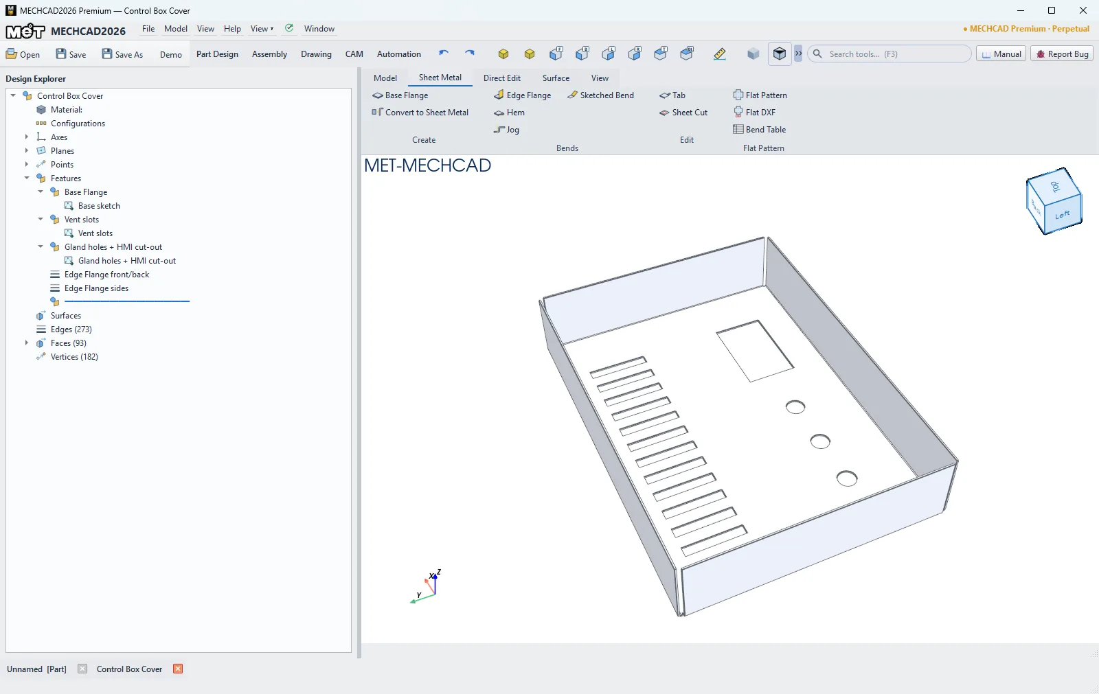
The Sheet Metal tab of the ribbon in the Part window:
| Group | Buttons |
|---|---|
| Create | Base Flange, Convert to Sheet Metal |
| Bends | Edge Flange, Hem, Jog, Sketched Bend |
| Edit | Tab, Sheet Cut |
| Flat Pattern | Flat Pattern, Flat DXF, Bend Table |
Steps
- Draw a sketch: a closed sketch = a flat plate, an open sketch (lines/arcs) = a bent profile.
- Click Base Flange, pick the sketch, then choose the Material and Gauge table thickness. Thickness, bend radius and K-factor are filled in from the table (you can change them). Click OK.
- Add flanges: click Edge Flange or Hem, then click straight edges of the sheet in the view (click again to remove). All picked edges become one feature.
- To bend along a line, draw a sketch with one straight line on a panel face, then use Jog or Sketched Bend.
- Add material with Tab or cut with Sheet Cut (a closed sketch on a panel face).
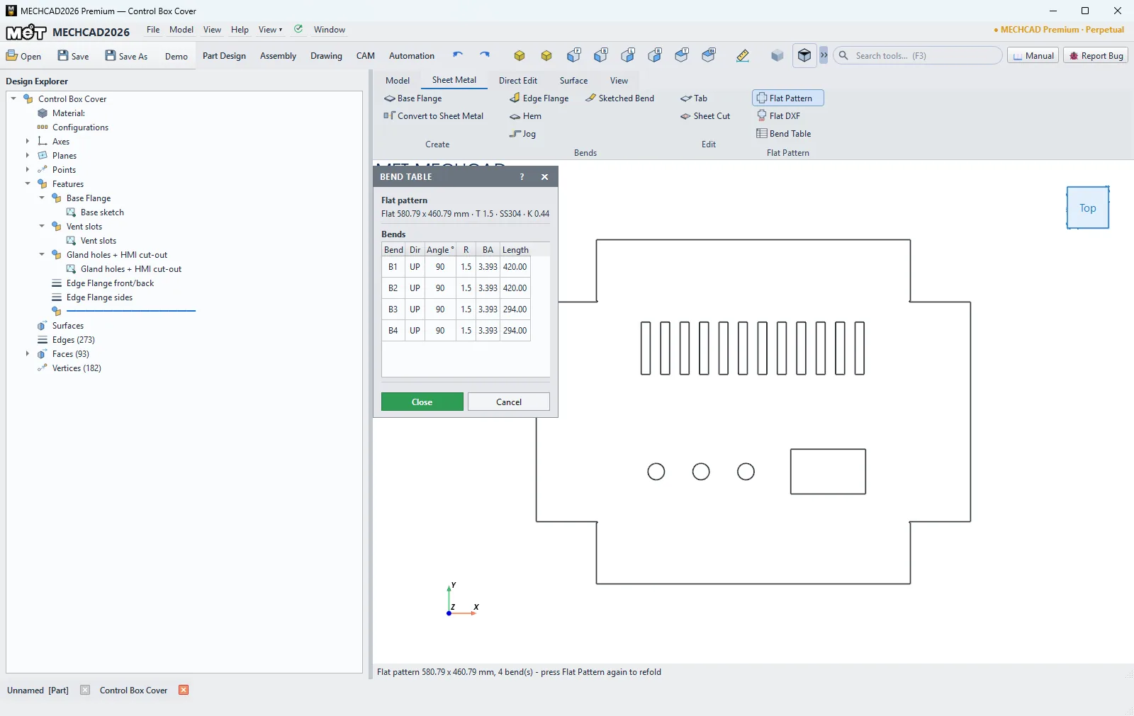
- Click Flat Pattern to unfold (click again to refold), Bend Table to see the bends, and Flat DXF to save the DXF file.
Base Flange
| Option | Default | Description |
|---|---|---|
| Sketch | - | Closed = flat plate, open = bent profile |
| Material | Mild steel SPCC / SS400 cold rolled | SS304, SPCC/SS400, Aluminium 5052-H32 or Custom |
| Gauge table thickness | 1.5 mm | 0.8, 1.0, 1.2, 1.5, 2.0, 2.5, 3.0 mm (fills in T, R and K) |
| Thickness T | 1.5 mm | Sheet thickness |
| Inside bend radius R | 1.5 mm | Inside bend radius |
| K-factor | 0.44 | Neutral axis position used for the unfold |
| Bend allowance | K-factor | K-factor / Bend allowance table / Bend deduction table |
| Table rows | 90° / 0 mm | Angle/value rows (used by the table modes) |
| Bend relief | Rectangular | Rectangular / Round (obround) / Tear (rip, no cut) / None |
| Relief width / Relief depth past bend | 0 (= T) | Size of the relief at the bend |
| Corner relief | Rectangular | Rectangular / Round / Tear (none cut) / None |
| Corner relief size | 0 (= T) | Size of the corner relief |
| Width (bent profile depth) | 50 mm | Sheet width for an open sketch |
| Flip material side | Off | Puts the material on the other side |
| Bent profile: mid-plane | Off | Centres the width on the sketch (open sketch) |
Edge Flange
| Option | Default | Description |
|---|---|---|
| Edges | - | Click straight edges of the sheet (top or bottom face) |
| Length | 20 mm | Flange length |
| Length measured to | Outer virtual sharp | Outer virtual sharp / Inner virtual sharp / Tangent (straight leg) |
| Bend angle | 90° | Bend angle (0.1–179°) |
| Flange position | Bend outside the edge | Bend outside the edge / Material inside (flush outer face) / Material outside (flush inner face) |
| Bend down (flip direction) | Off | Bends downward |
| Inside radius | 0 (= sheet R) | Bend radius for this flange |
| Offset from edge start / end | 0 mm | Sets the flange back from the edge ends |
| Bend relief | Sheet default | Uses the sheet setting, or pick one |
Hem
| Option | Default | Description |
|---|---|---|
| Hem type | Closed (flattened) | Closed (flattened) / Open (with gap) / Teardrop |
| Length | 8 mm | Hem length (teardrop: 0 = to the panel) |
| Gap (open hem) | 0 mm | Gap of an open hem |
| Teardrop radius | 0 (= T) | Teardrop radius |
| Teardrop angle | 230° | Teardrop angle (181–329°) |
| Position | Outside the edge | Outside the edge / Inside (folded back in) |
| Fold down (flip direction) | Off | Folds downward |
Jog and Sketched Bend
Both commands use a sketch with one straight line drawn on a panel face.
| Option | Default | Description |
|---|---|---|
| Offset (Jog) | 10 mm | Step height of the jog |
| Offset measured (Jog) | Face to face (same side) | Face to face (same side) / Inside (gap between) / Overall (outside faces) |
| Jog angle / Bend angle | 90° | Bend angle |
| Inside radius | 0 (= sheet R) | Bend radius |
| Fix projected length (Jog) | On | Keeps the projected length |
| Bend down / Jog down | Off | Bends downward |
| Bend the other side / Move the other side | Off | Swaps the side that moves |
Other commands
| Command | What it does |
|---|---|
| Convert to Sheet Metal | Turns a constant-thickness solid with round bends (for example an imported STEP part) into sheet metal. Thickness and radii are read from the solid; the largest flat wall stays fixed. Only Material and K-factor (0.44) are set. |
| Tab | Adds material from a closed sketch drawn on a panel face (it must touch the panel) |
| Sheet Cut | Cuts through the panel along a closed sketch. Tick Cut the flat pattern to cut across bends on the unfolded part, then refold |
| Flat Pattern | Toggles the unfolded/folded part. The status bar shows the flat size and the number of bends |
| Flat DXF | Saves a DXF in mm with layers OUTER, INNER, BEND_UP, BEND_DOWN (dashed) and BEND_NOTES |
| Bend Table | Shows the flat size, T, material, K and the bend list: Bend, Dir, Angle, R, BA, Length |
Note: Sheet Metal is available in MECHCAD Expert and Premium. On Standard the tab is visible, but clicking a command shows an upgrade notice. Create a Base Flange (or Convert to Sheet Metal) first; the other commands need it. If the part is already sheet metal, clicking Base Flange again opens Tab instead.