
What it does
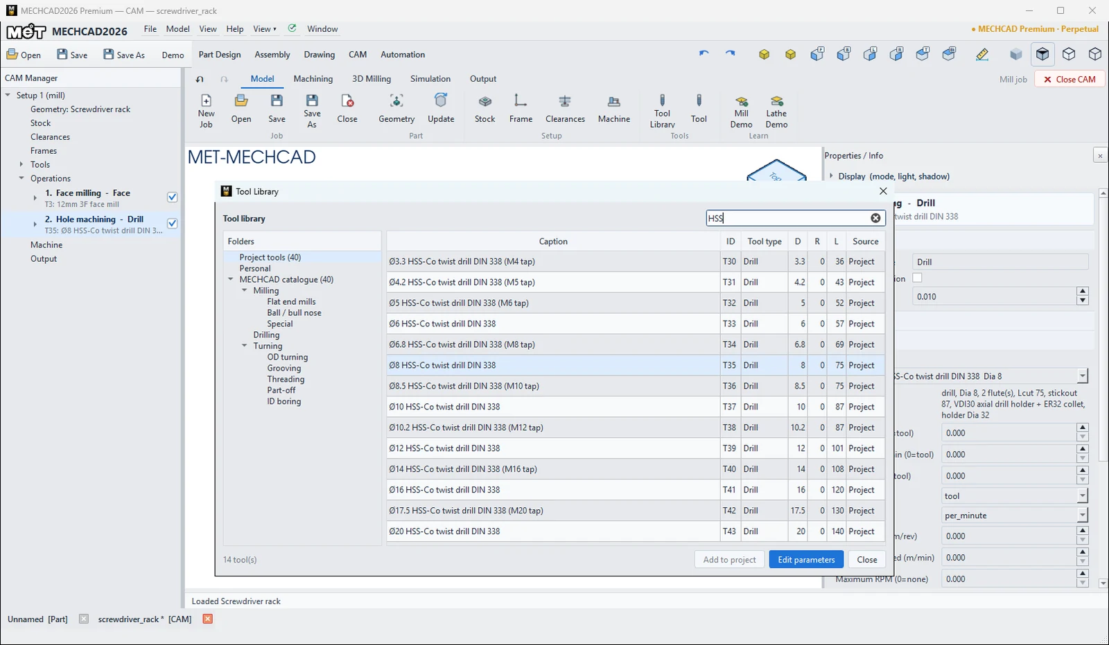
Manages the tools used in the job. The tools under Project tools are the tools of this job.
Where to find it
Model › Tools › Tool Library and the Tools node in the CAM Manager
| Item | Description |
|---|---|
| Search caption / ID / group / Ø... | Search for tools by name, ID, group or size (for example drill 8). |
| Folders | Project tools, Personal and MECHCAD catalogue, each split into tool groups (see the table below). The window opens on the group of the selected operation. |
| Caption, ID, Tool type, D, R, L, Source | Columns |
| New tool... | Creates a new tool in the Tool box. |
| Add to project | Copies a catalogue or Personal tool into the job. |
| Edit parameters | Edits the settings (or double-click). |
Standard tool library by group
The MECHCAD catalogue holds standard metric tools you can buy off the shelf (IDs T100 and up) in addition to the original tool set. The S / F values of the standard tools are generic starting values; adjust them for your material and actual tool.
| Group | Examples in the library |
|---|---|
| Face | Face mills D32–80 (R0.8) |
| Flat | 2F / 3F / 4F end mills D1–20, plus long-reach |
| Bull nose | D4–20, corner R0.5 and up |
| Ball | D1–16 |
| Drill | HSS drills D1–13 in 0.5 mm steps, tap drills and carbide drills |
| Spot/Center | 90° spot drills |
| Tap | Taps M3–M12 |
| Reamer | H7 reamers |
| Bore | Bore heads |
| Chamfer | 90° and 60° chamfer mills with tip diameter |
| Thread mill | M4 and up |
| Slot/T-slot | T-slot and 45° / 60° dovetail |
| Corner round | R0.5–R5 |
| Engrave | 60° V engravers |
| Lathe | Turning tools, split into OD turning / ID boring / Grooving / Threading / Part-off |
The same groups are used wherever you pick a tool: the Tools node in the CAM Manager lists the job tools by group (for example Drill (5)), and the tool selector in the Tool section of the operation box lists the tools by group, with the operation's own group first. Each row shows the Ø, and the Filter tools: name, group, Ø ... box narrows the list.
Main tool settings
| Field | Description |
|---|---|
| Tool name / Tool type | Name / type (endmill, ball, bull, drill, center_drill, chamfer, corner_round, engraver, tap, reamer, boring, threadmill, tslot, dovetail, turning) |
| Included / point angle (deg), Tip diameter | Included angle of the tip and the flat tip diameter (chamfer mills, engravers, spot drills, and the drill point angle) |
| Diameter / insert width, Flutes, Corner / nose radius | Tool size |
| Cutting length (0 = 3×D), Stickout | Flute length and stickout |
| Holder diameter, Holder length, Arbor / holder style | Holder (for example BT40-ER32, HSK63A, PCLNR 2020), used for collision checking |
| Turning insert ISO code, shape, orientation, holder hand | Turning tool settings |
| Turret station, Geometry/wear offset, Tool-tip orientation code | Turret settings (turning) |
| Spindle direction, Default RPM, Default cut feed, Default plunge feed | Default spindle speed (6000) and feeds (300 / 100) |
| Default stepover / stepdown | Default stepover (0.4×D) / stepdown (1) |
| Tool material, Default coolant, CSS surface speed, maximum RPM | Tool material, coolant, surface speed |
Chamfer tools
A chamfer mill uses Included angle (A) (for example 90° or 60°) and Tip dia (d) (the flat tip). MECHCAD uses these two values to put the cone exactly on the chamfer line. A Chamfer operation sets Chamfer width (default 0.5) and Tip offset (how far the tip goes below the bottom of the chamfer, default 0) in the Path Setting section of the operation box, and shows the computed position, for example Tool axis 3.000 mm off the edge, tip at Z-3.000 (A90, tip d2). If the chamfer is too wide for the tool, you see chamfer too wide for the tool. If you click a chamfer face that is already in the model, MECHCAD takes the sharp edge and the width from that face.
The Tool box (create / edit a tool)
Click New tool..., or right-click a tool in the CAM Manager › Edit Tool..., to open the floating Tool box. It has the Cutter / Holder / Speeds tabs next to a drawing of the tool with its dimension letters (D, L, FL, SD, R, A ...).
| Item | Description |
|---|---|
| Type / Subtype | Mill (End, Ball, Bull / Radius, Chamfer, Spot, Thread mill, T-slot, Dovetail, Engrave (V), Corner round, Bore head), Drill (Drill, Spot, Reamer), Tap, Lathe (Turning insert) |
| Cutter | Cutter dia (D), Tool length (L), Flute length (FL), Shank dia (SD), Radius (R), Included angle (A), Tip dia (d), Pitch (P), Flutes (F); only the fields of that type are shown |
| Holder | Holder, Holder dia, Holder / gauge length, Stickout (gauge to tip) |
| Speeds | Spindle S (rpm), Feed F (mm/min), Plunge (mm/min), Coolant, H offset, D offset (= tool no. means the tool number is used) |
| Add to Lib / Load Tool Shape / Save All / Load All | Stores the tool in your Personal library, and imports / exports tools as .mettool files |
| OK / Apply / Reset / Delete / Cancel | Apply / discard / delete the tool |
When you edit a tool that is in use, the toolpaths of the operations using it are marked for recalculation, and the cutter in the simulation changes with it (see Simulation).
Try it: Choose the right tools for a screwdriver rack
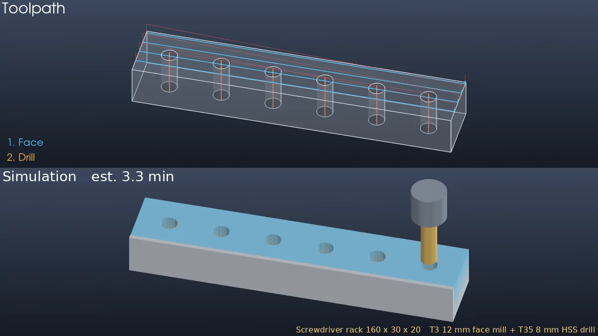
A 160 × 30 × 20 bench rack with six Ø8 holes keeps your screwdrivers standing. Out of the box, the operations would use a 6 mm end mill and a 6 mm drill. Here you pick the right cutters from the library.
- Model a 160 × 30 × 20 block. On the top face, draw six Ø8 circles at Y 15 and X 15, 41, 67, 93, 119 and 145, then Extrude Cut them Through All.
- CAM › New Job › Mill Template. In Stock, choose Part + allowance (0.5 mm on top to face) and set Support height (parallels) to 5 so the drill can break through.
- Click Model › Tools › Tool Library. Type
HSSin the search box and select Ø8 HSS-Co twist drill DIN 338 (T35). It is already in Project tools. (Tools from the MECHCAD catalogue folder are copied in with Add to project.) - Click Edit parameters and set Default RPM to 1000.
- Add a Face on the top face. In the Tool section of the operation box, choose T3 12mm 3F face mill. It needs far fewer passes than the 6 mm default.
- Add a Drill: click all six hole walls and press Enter. Smart Hole picks the first Ø8 drill of the job for you, T35, and sets Depth to 22.903 (20 mm of plate + the 118° point + 0.5 mm to break through). Set Peck depth to 4.
- Simulate. The estimated time is about 3.3 min, and the G-code changes tools with
T35 M06andS1000.
Challenge: Add a Chamfer on the top edge of one hole with T20 6mm 90deg Chamfer Mill so the screwdrivers slide in easily.
Note: CAM is available only in MECHCAD Premium (and during the trial).