
What it does
- Profile mills along an edge (outside, inside or on the line) with arc lead-in and lead-out. Cutter compensation is done by the computer, or G41/G42 + a D number is output so the control compensates (Tool Compensation).
- Ramp Cut ramps down continuously along the selected edge.
Where to find it
Machining › 2.5D Milling › Profile / Ramp Cut
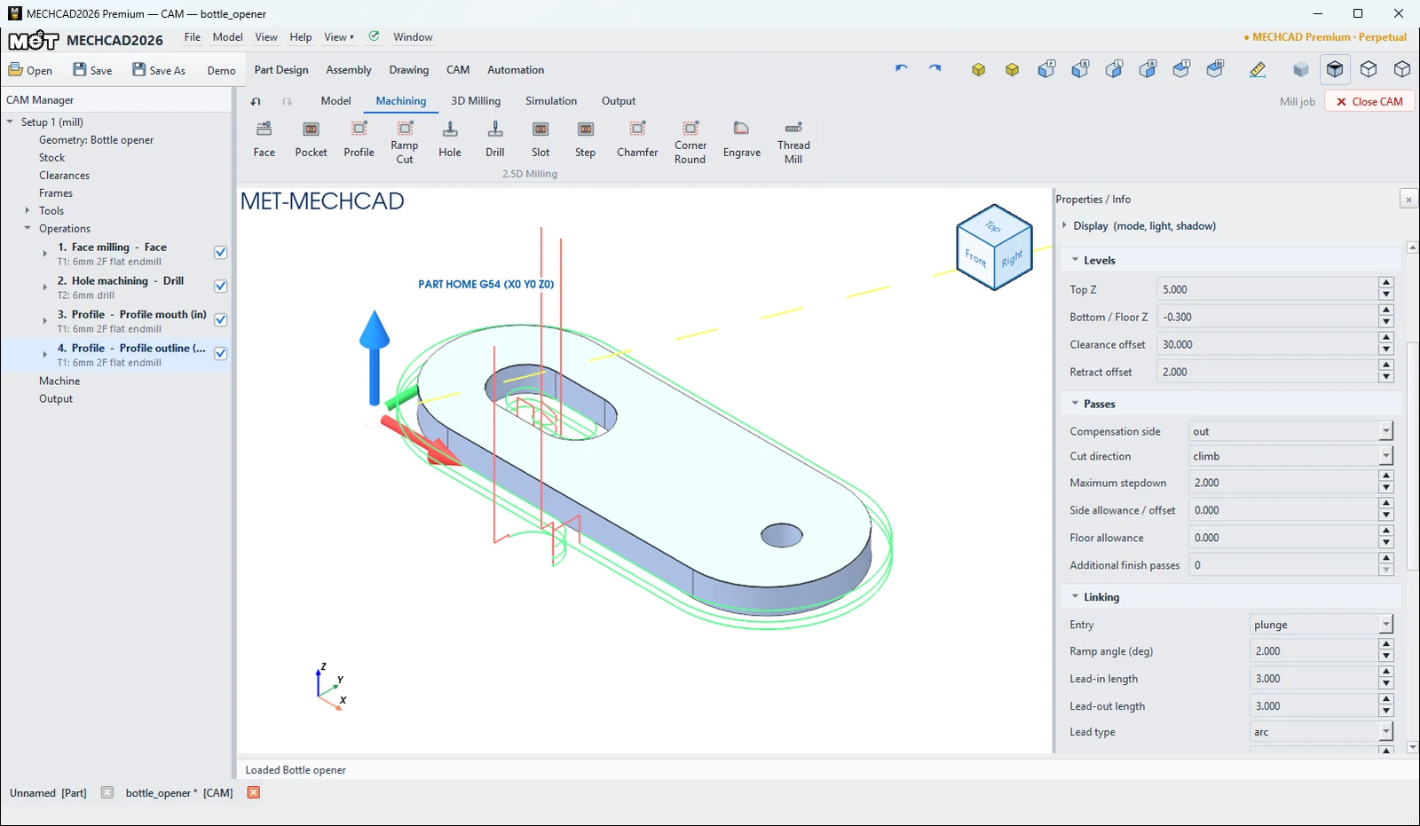
Steps
- Click Profile.
- Click an edge in the view (a continuous chain of edges is selected automatically), then press Enter.
- Set Compensation side, Maximum stepdown, Lead type and Tool Compensation, then Simulate.
| Key defaults | Value |
|---|---|
| Compensation side | out |
| Maximum stepdown | 1 mm |
| Lead type | arc |
| Tool Compensation | None / Computer (see the next section) |
| D register | 0 (= the tool number) |
| Edge chain | auto / loop / tangent / circle |
Tool Compensation (D-offset)
Set it in the Path Setting section of the operation box for Profile, Ramp Cut, Chamfer and Corner Round (the Linking page under Parameters also has the Tool Compensation and D register (0=tool no.) fields).
| Tool Compensation | Resulting G-code |
|---|---|
| None / Computer | MECHCAD computes the cutter-centre path; no G41/G42 in the NC (default). |
| Offset (G41/G42 on contour) | The NC follows the actual part contour, with G41/G42 + D on the lead-in and G40 on the lead-out. The control offsets the cutter by the radius in the D register. |
| Wear (G41/G42 on centre path) | The NC follows the cutter-centre path, plus G41/G42 + D. The D register holds only the wear, for size adjustment at the machine. |
D register is the radius register output with G41/G42. It is active when Offset or Wear is chosen. A value of 0 (shown as tool no.) means the tool's D offset is used (the Speeds tab of the Tool box), and if the tool has none, the tool number.
Chamfer (V-cutter chamfer, width 0.5 mm), Corner Round (R1 round) and Engrave (engrave along a line) use the same edge selection. See Other 2.5D operations.
Double-click an operation in the CAM Manager to open its operation box, where you can edit every value. Its Parameters section has the pages General, Geometry, Tool, Levels, Passes, Linking and Stock (see Operation Parameters for the meaning of each field).
Try it: Cut out a bottle-opener keychain
An 80 × 30 × 5 aluminium keychain with a slot that pops bottle caps. Two Profiles do the work: one inside the opener slot, one around the outline.
- Model the outline as a slot shape 80 mm long and 30 mm wide (R15 ends) and Extrude it 5 mm. On the top face, draw a 22 × 12 slot whose ends are centred at X 16 and X 26 (Y 15), and a Ø6 circle at X 68 Y 15. Extrude Cut both Through All.
- CAM › New Job › Mill Template. In Stock, choose Part + allowance (0.5 mm on top to face) and set Support height (parallels) to 3.
- Add a Face on the top. Add a Drill on the Ø6 hole and set Depth to 5.5.
- Click Profile, click the top edge of the opener slot and press Enter. Set Compensation side to
inand Bottom / Floor Z to −0.3. In Linking, set Lead arc radius to 2, Lead-in length to 1 and Lead-out length to 1. The default lead (0.8 × D = 4.8 mm) is too big for a 12 mm wide opening and would cut into the opposite wall. - Click Profile again, click the top outer edge and press Enter. Keep Compensation side
outand set Bottom / Floor Z to −0.3. - Simulate (about 2.9 min). The opener drops out of the blank, so hold the blank with screws or tape outside the outline.
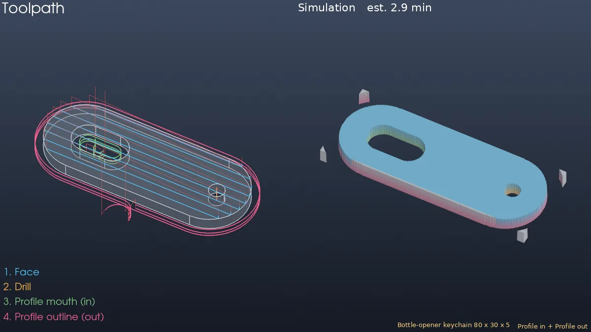
Challenge: Set the outline Profile's Tool Compensation to Offset (G41/G42 on contour) and look in the G-code for G41/G42 with the D number on the lead-in and G40 on the lead-out. Then enter another D register number and generate the G-code again.
Note: CAM is available only in MECHCAD Premium (and during the trial).