
What it does
Sets up the CNC machine and the post-processor used to generate G-code. You can edit the G-code format yourself.
Where to find it
The Machine node in the CAM Manager, or Model › Setup › Machine / Output › Post
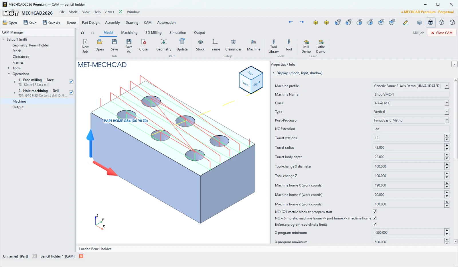
| Option | Description |
|---|---|
| Machine profile | Custom / legacy (no envelope), Generic Fanuc 3-Axis Demo [UNVALIDATED], Generic Fanuc 2-Axis Lathe Demo [UNVALIDATED] |
| Machine Name / Class / Type | Name / 3-Axis M.C. or Lathe / Vertical or Horizontal |
| Post-Processor | FANUC_MET 3Axis, FanucBasic_Metric, FanucBasic_Inch, Fanuc15i_3axis, BASIC_ISO, GRBL, LinuxCNC, fanuc_lathe, fanuc_mill, grbl |
| NC Extension | G-code file extension (.nc) |
| Turret stations / radius / body depth, Tool-change X / Z | Turret settings (turning) |
| Machine home X/Y/Z | Machine home position |
| NC: G21 metric block at program start | Adds G21 at the start of the program |
| NC + Simulate: machine home -> part home -> machine home | Moves through home |
| Enforce program-coordinate limits / X/Y/Z minimum / maximum | Allowed coordinate limits |
| Commissioning status | Status of calibration against the real machine |
| G-code Pattern (editable) | JSON G-code format of the post |
Edit the G-code format (pattern)
The G-code Pattern field has the keys name, unit (mm/inch), prog, header[], tool_change[], rapid, feed, arc_cw, arc_ccw, footer[] and the placeholders {PROG} {WCS} {TOOL} {RPM} {SAFE_Z} {X} {Y} {Z} {I} {J} {FEED}. Your edits are saved per post in that job. If the JSON is invalid, you see Pattern JSON error: ….
Note: fanuc_lathe, fanuc_mill and grbl are programmed posts (class-based post — no editable pattern). Profiles marked [UNVALIDATED] have not been calibrated against a real machine. Always test the first program on the machine with care.
Try it: Put your own header on a pencil holder program
An 80 × 40 × 30 desk pencil holder with six Ø10 holes, 25 mm deep. You name your machine, choose FanucBasic_Metric, and add your own program number and comment to the program.
- Model an 80 × 40 × 30 block. Draw six Ø10 circles at X 15 / 40 / 65 and Y 11 / 29 and Extrude Cut them 25 mm.
- CAM › New Job › Mill Template. Add a Face with T3. Add a Drill on the six hole walls with cutter T37 Ø10 HSS-Co twist drill, Peck depth 5 and Depth 25. (For blind holes the default depth goes down to Z0, so you must set it.)
- Click Machine in the CAM Manager. Set Machine Name to
Shop VMC-1and Post-Processor toFanucBasic_Metric. - In G-code Pattern (editable), change
"prog": 1000to"prog": 2610. In"header", add"(PENCIL HOLDER - OP1)"after"O{PROG}". Apply. - Output › G-code. The program now starts with
%,O2610,(PENCIL HOLDER - OP1)andG21 G17 G40 G49 G80 G90.
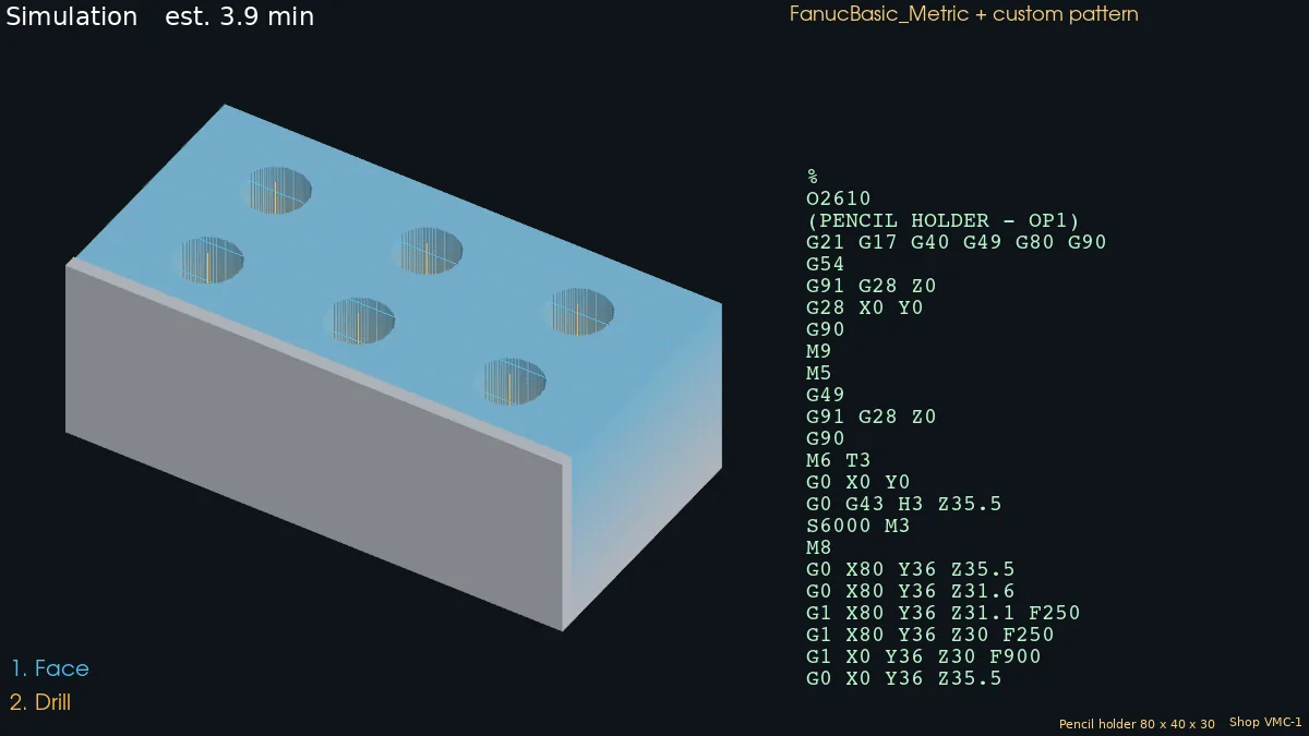
Challenge: Clear NC + Simulate: machine home -> part home -> machine home and generate again. The G28 X0 Y0 line after the header disappears.
Note: CAM is available only in MECHCAD Premium (and during the trial).