
What it does
Sets up the job before you create operations: the stock size, the work coordinate system (WCS) and the tool clearance heights.
Where to find it
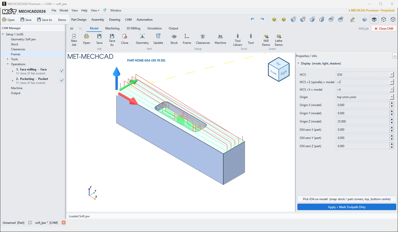
Model › Setup › Stock / Frame / Clearances, or click the node in the CAM Manager
Stock
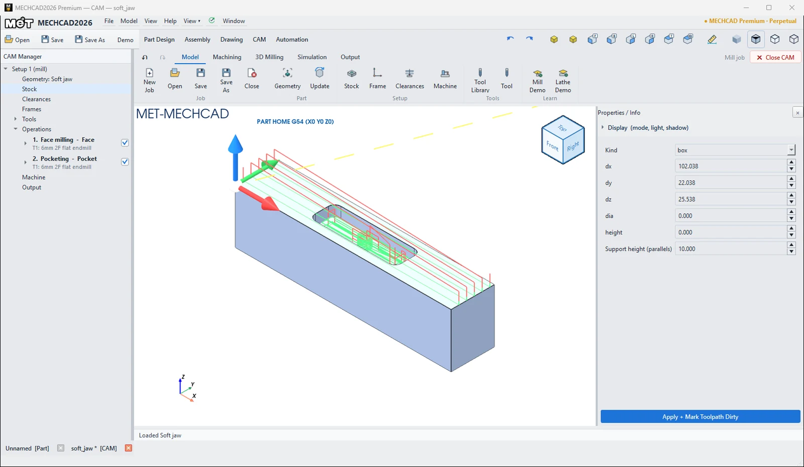
A new job starts with a stock exactly the size of the part bounding box (no allowance). To add material or use your real raw size, choose a mode in the Stock box. The panel shows only the fields of that mode. A summary box at the top gives the part size (Part box: … mm) and the resulting stock (Stock: …, with its from … to … coordinates). Edits apply at once: the translucent stock in the viewport follows, every toolpath is marked for recalculation, and the old simulation is cleared. The Stock node in the CAM Manager shows the kind and size, for example Part box 60 x 40 x 20.
Milling
| Stock | Description |
|---|---|
| Part (default) | A box exactly the size of the part bounding box, no allowance (the default of a new job). |
| Part + allowance | The part box plus a separate allowance on each side: Allowance -X, +X, -Y, +Y, -Z (below), +Z (top). When you first choose it, MECHCAD fills in 1 / 1 / 1 / 1 / 0 / 0.5. |
| Manual size | Type the size yourself (Length X, Length Y, Height Z) and choose Placed: At position (min corner) (enter Position X / Y (min corner) and Position Z (bottom)) or Centred on part (XY) (centred on the part in XY, bottom on the part bottom, the extra height on top). |
| Round bar (cylinder) | A Bar diameter × Bar length bar along Bar axis (Z / X / Y), centred on the part. A bar lying along X or Y is simulated as its enclosing box. |
| From CAD file | Uses the bounding box of the part in a CAD file as the stock. Click Stock from CAD file... to choose the file. |
| Support height (parallels) | Height of the parallels |
Turning
Turning uses a round bar along the spindle axis (+Z). The front of the bar sits the face allowance in front of the part face; the rest of the length is behind the part, where the chuck grips it.
| Option | Description |
|---|---|
| Bar stock | Standard bar (default) = the next standard bar size that leaves at least 1 mm on the part diameter (at most part Ø + 4), Bar = part OD = the largest part diameter, Manual D x L = your own size |
| Diameter D, Length L | Bar size (mm). Typing D or L switches the mode to Manual D x L automatically. |
| Face allowance (in front of part) | Material left in front of the part for the facing operation. Default 2 mm. |
The summary box shows Part: OD … x L … mm, Stock: … D… x L… and the face allowance and grip length behind the part (… mm to face, … mm behind the part (chuck grip)). When you change the bar, turning operations that still use values from the old bar (bar radius, face stock, approach clearance) follow the new bar. Values you typed yourself are kept.
Frame (WCS)
| Option | Description |
|---|---|
| WCS | G54–G59 |
| WCS +Z (spindle) = model / WCS +X = model | Machine axis directions relative to the part (±X, ±Y, ±Z) |
| Origin | custom, top xmin ymin, top xmin ymax, top xmax ymin, top xmax ymax, top center, bottom xmin ymin |
| Origin X/Y/Z (model) / G54 zero X/Y/Z (part) | Zero point coordinates |
| Flip (turn the part over) / Rotate about Z | Turns the part over and rotates it about Z |
| Work zero (G54) on stock | Puts G54 on a point of the stock: a corner, an edge midpoint or the centre of the top (top …), bottom centre, bottom xmin ymin, or custom |
| Pick G54 on model | Click an orange point on a corner/centre of the stock or part (Esc = cancel) |
Clearances
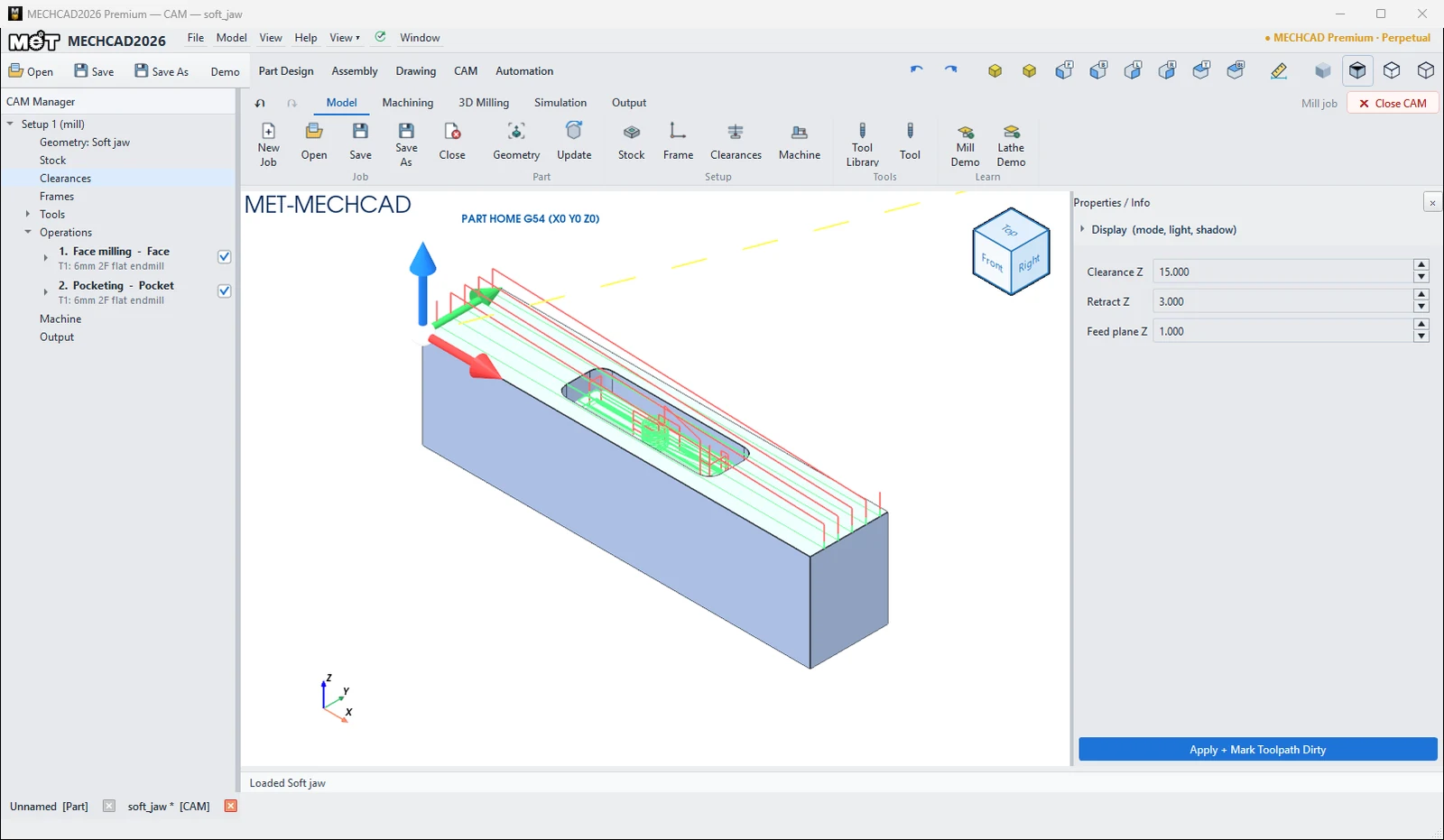
| Option | Default | Description |
|---|---|---|
| Clearance Z | 25 | Safe level for rapid moves |
| Retract Z | 5 | Retract level between operations |
| Feed plane Z | 1 | Level where feed cutting starts |
Each panel ends with the Apply + Mark Toolpath Dirty button (applies the values and marks the toolpaths for recalculation).
Try it: Set up a vise soft jaw on parallels
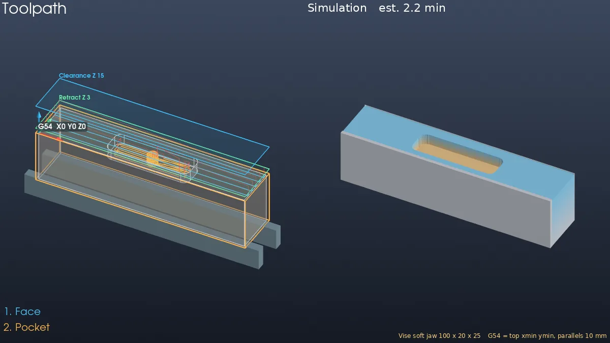
Soft jaws are usually the first thing a machinist makes for their own vise. Here it is a 100 × 20 × 25 aluminium jaw with a 40 × 12 nest pocket. You put G54 on the top front-left corner, sit the jaw on 10 mm parallels and set tight clearances.
- Model the jaw: a 100 × 20 rectangle Extruded 25 mm. On the top face, sketch a 40 × 12 rectangle 30 mm from the left and 4 mm from the front, with R3 corners, and Extrude Cut it 5 mm.
- CAM › New Job › Mill Template.
- Do the Frame first. Set Origin to
top xmin yminand click Apply + Mark Toolpath Dirty. The top of the part is now Z0 and the front-left corner is X0 Y0. The stock is fitted to the part again. - Then the Stock: choose Part + allowance (MECHCAD fills in 0.5 mm on top, so there is material to face) and set Support height (parallels) to 10, then click Apply. (Do the stock after the frame, because applying the frame fits the stock again.)
- Clearances: Clearance Z 15, Retract Z 3, Feed plane Z 1, then Apply.
- Add a Face on the top face and a Pocket on the nest floor. The pocket now runs from Top Z 0 to Floor Z −5.
- Simulate (about 2.2 min) and look at the G-code: the face pass cuts at
Z0and the pocket stops at Z−5.
Challenge: Change WCS to G55 and generate the G-code again. The program header now calls G55 instead of G54.
Note: CAM is available only in MECHCAD Premium (and during the trial).