
What it does
Brings the edges of the part or of another sketch into the current sketch. Use them as snap points, to add dimensions, or as real shapes for a feature.
Where to find it
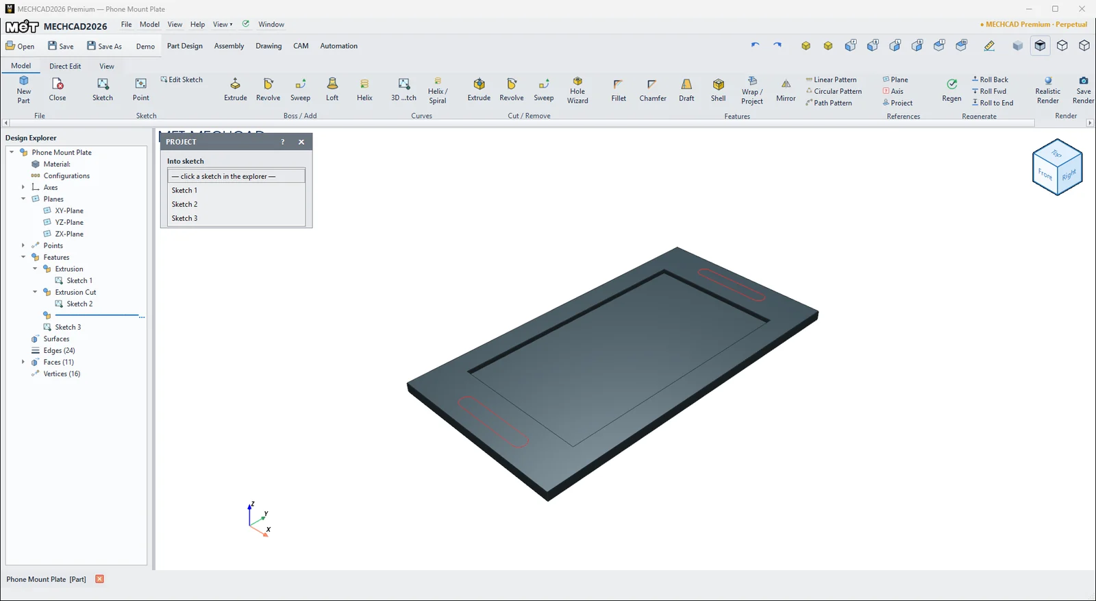
- While sketching: Reference / Snap › Project / Project All / Project Face
- Part ribbon: Model › References › Project (if no sketch is open yet, it first asks which sketch to project into)
| Command | Meaning |
|---|---|
| Project | Choose what to project: Body outline (silhouette), Body edges (all), Support face edges and other sketches |
| Project All | Projects all edges, the outer outline and all other sketches as dashed reference lines in one click |
| Project Face | Copies the edges of the face you are sketching on as reference lines |
| Wrap | Finishes the sketch and opens the Wrap / Project command |
Project to Sketch box
| Option | Meaning |
|---|---|
| Geometry / Sketches | Tick the items to project |
| Select All | Selects everything |
| Pick faces in the view | Click faces in the view to select them |
| Maintain Association | The projected lines update with the part (default: on) |
| Project As | References (dashed) reference lines / Figures real lines |
Note: Projected lines can be trimmed or deleted right away. Right-click a reference › Convert to Normal (Detach Reference) breaks the link to the part and leaves an editable dashed construction line. To use it as a profile edge, right-click it again › Convert to Normal Geometry. Lines projected as Figures become the profile only while the sketch has no shapes of your own. As soon as you draw your own shapes, Finish Sketch uses only those, and the projected lines stay as guides.
Try it: Bike phone-mount plate
A handlebar phone mount needs a pocket for a grip pad and two slots for the straps. Project Face gives you the plate edges as dashed guides, so everything lines up with the outline without any measuring from the origin.
- Click Sketch and press Enter (XY-Plane). Choose Center Rect, click the origin, type 80, press Tab, type 150 and press Enter. Click Finish Sketch, then Extrude the plate 4 mm.
- Right-click the top face › Insert Sketch on Surface, then click Reference / Snap › Project Face. The four plate edges appear as dashed reference lines.
- Choose Center Rect, click the centre of the face, type 60, Tab, 110 and press Enter. Click Finish Sketch, then Extrude Cut 2 mm. The dashed references are only guides. Only your rectangle is cut, so you get the pocket.
- Right-click the top face again › Insert Sketch on Surface › Project Face. Draw a horizontal Slot near each short edge. With Smart Dimension, set each slot to 30 mm between the end centres, R3 on an end arc (6 mm wide), 9 mm from the slot centre line to the dashed short edge and 25 mm from the left end centre to the dashed long edge.
- Click Finish Sketch, then Extrude Cut with Through All.
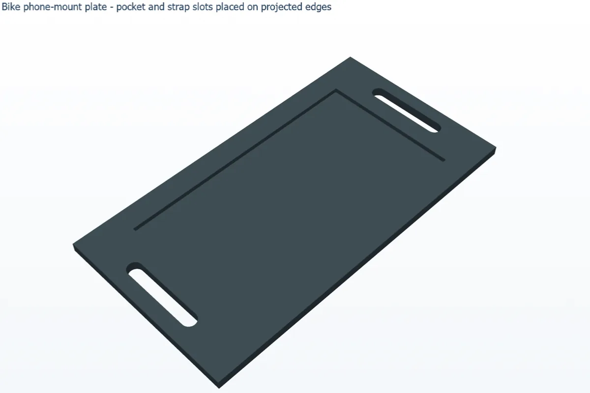
Challenge: Change the plate to 90 x 160 mm. Because the pocket and slots are dimensioned to the projected edges (Maintain Association is on), they follow the new outline.