
What it does
Starts a new CAM job, chooses the machine type, and defines the workpiece to cut.
Where to find it
Model › Job › New Job / Open / Save / Save As / Close and Model › Part › Geometry / Update
Steps
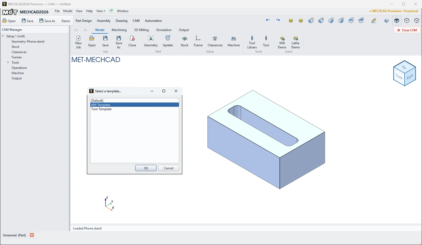
- Click New Job. If a job is already open, you are asked Discard the current operations and start a new job?
- Choose a template, then click OK.
- The part from the open Part Design is used automatically. If there is none, click Geometry and choose a file (CAD (*.step *.stp *.igs *.iges *.stl *.metprt)).
- Save with Save (
.metcam).
| Template | Settings applied |
|---|---|
| [Default] / Mill Template | Box stock exactly the size of the part bounding box, no allowance (Part (default); the Stock node shows for example Part box 60 x 40 x 20), Clearance Z = top surface + 15, Frame G54, Post FANUC_MET 3Axis, machine 3-Axis M.C. Vertical, extension .nc |
| Turn Template | Round bar stock (Standard bar (default)) Ø = the next standard bar size that leaves at least 1 mm on the diameter (at most part Ø + 4), length = gripping length + part length + 2 (face allowance), machine Lathe Horizontal, Post fanuc_lathe, 12-station turret |
| Command | Description |
|---|---|
| Open | Opens a .metcam file (the original part file must exist). |
| Save / Save As | Saves a .metcam file (a sample job must be saved to another folder with Save As). |
| Close | Closes the job (asks Save / Discard / Cancel). |
| Geometry | Select/import the workpiece. |
| Update Geometry | Reloads the original part. Stock and operations are kept, but toolpaths must be recalculated. |
To add material around the part, type your own stock size, or set a D × L bar for turning, click the Stock node and choose a mode in its panel (see Stock, Frame (WCS) and Clearances).
Note: If the original part was edited after the toolpaths were created, you see Source geometry is out of date. Click Update Geometry.
Try it: Start a job for an aluminium phone stand
An 80 × 50 × 30 block with a 13 mm cradle slot that holds your phone upright on the desk. This example is all about the job itself: template, stock, clearance, G54 and saving.
- In Part Design, sketch an 80 × 50 rectangle on XY from the origin and Extrude it 30 mm.
- Sketch on the top face: a 70 × 13 rectangle 5 mm from the left edge and 15 mm from the front edge, with R4 corners. Extrude Cut it 15 mm.
- Open the CAM tab and click New Job. Choose Mill Template and click OK. The part is picked up from Part Design automatically.
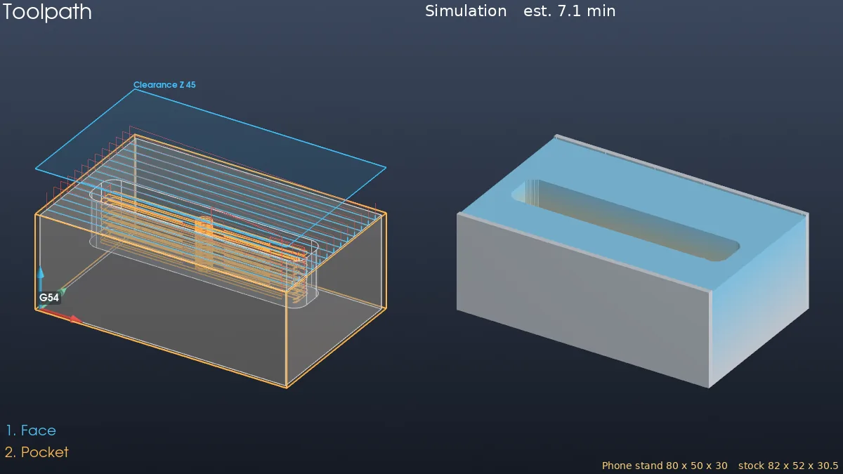
- Check what the template created. Click Stock: the stock is exactly the part box (Part box: 80 x 50 x 30 mm). Change Stock to Part + allowance. MECHCAD fills in Allowance -X, +X, -Y, +Y of 1 and Allowance +Z (top) of 0.5, which gives an 82 × 52 × 30.5 stock with material on top to face. Click Clearances: Clearance Z 45 (top + 15). Click Machine: Generic Fanuc 3-Axis Demo with the FANUC_MET 3Axis post. Click Frame: G54 at the model origin, so Z0 is the bottom of the part.
- Add a Face on the top face and a Pocket on the floor of the slot, then Simulate. The estimated time is about 7.1 min.
- Click Save and name the job
phone_stand.metcam.
Challenge: Export the stand as a STEP file, then click Geometry and load that file instead of the Part Design body. Do the stock and clearance come out the same?
Note: CAM is available only in MECHCAD Premium (and during the trial).