
What it does
Part Design builds parametric 3D parts. Every feature is recorded as history in Design Explorer. You can edit a value at any time and the part recalculates.
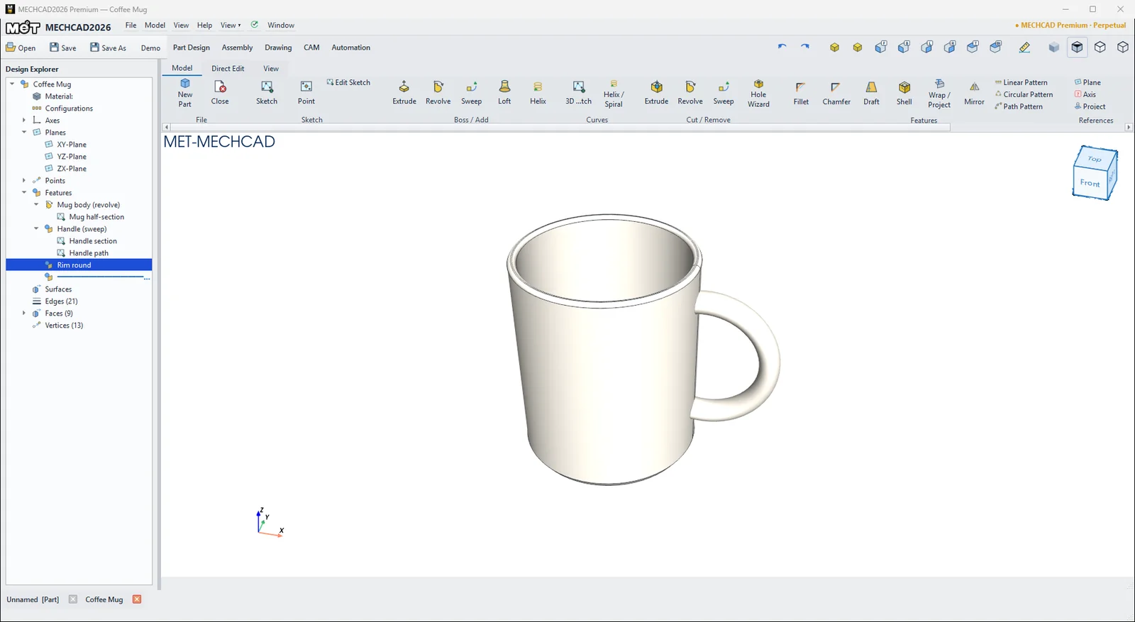
Typical workflow
- Create a Sketch on a plane or a face.
- Add material with a feature: Extrude, Revolve, Sweep, Loft, Helix.
- Remove material: Extrude Cut, Revolve Cut, Sweep Cut, Hole Wizard.
- Finish: Fillet / Chamfer, Draft, Shell, Wrap / Project.
- Repeat: Mirror, Linear / Circular Pattern, Path Pattern.
- Set the material and color and the Part Properties for drawings and BOM.
- Save as
.metprt.
Part Design ribbon



For details of every group, see Ribbon and Command Search.
Right-click in the view
- Empty space: Measure, Size Box, Sketch, Edit Sketch, Boss (Extrude/Revolve/Sweep/Loft/Helix), Cut (Extrude/Revolve/Hole Wizard), Fillet, Chamfer, Shell, Mirror, Linear/Circular Pattern, Plane, Rebuild
- Face: Measure, Insert Sketch on Surface, feature color, Edit Feature, Edit Child Sketch, Suppress/Delete Feature, Insert Offset Plane from This Face…, Fillet/Chamfer Edges of This Face, Edit Face Color, Edit Solid Color