
What it does
A constraint sets a geometric relation, such as parallel, perpendicular or tangent, so the sketch keeps its shape when you change a dimension.
Where to find it
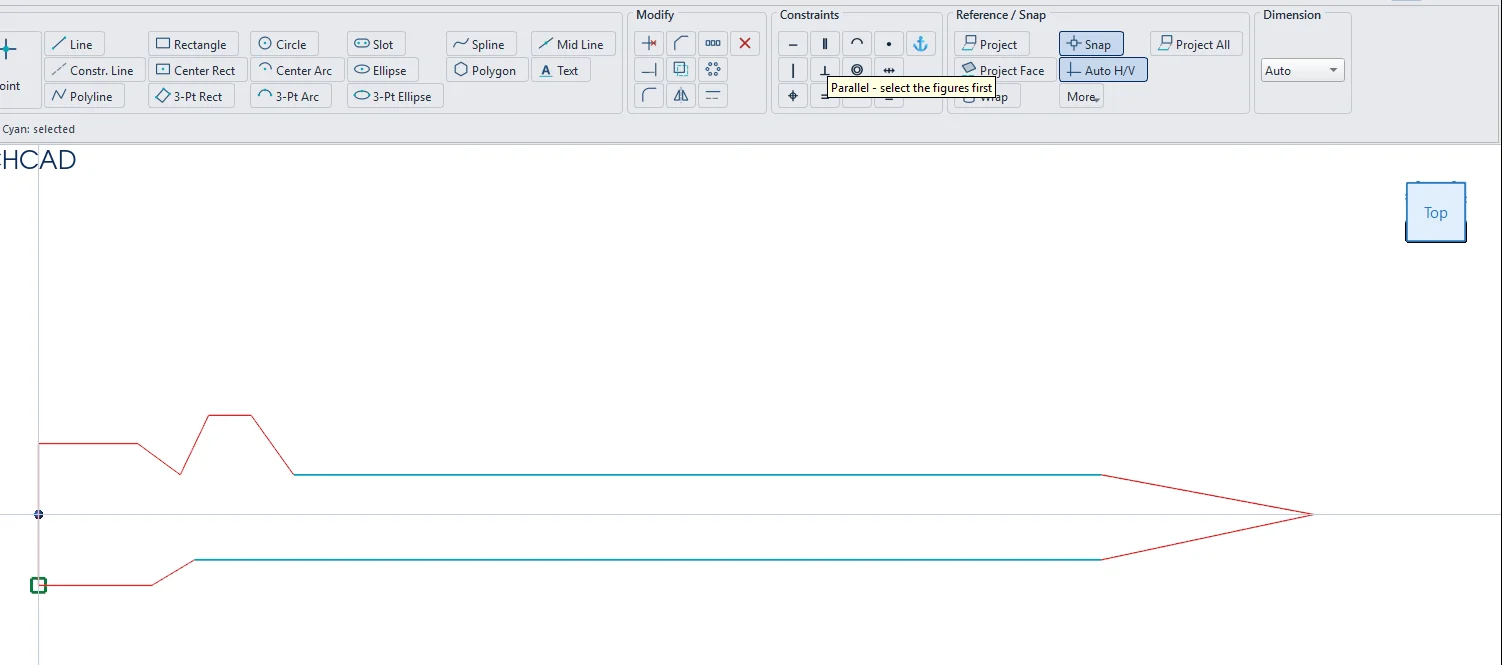
- Sketch ribbon › Constraints group (icons; hover to see the name:
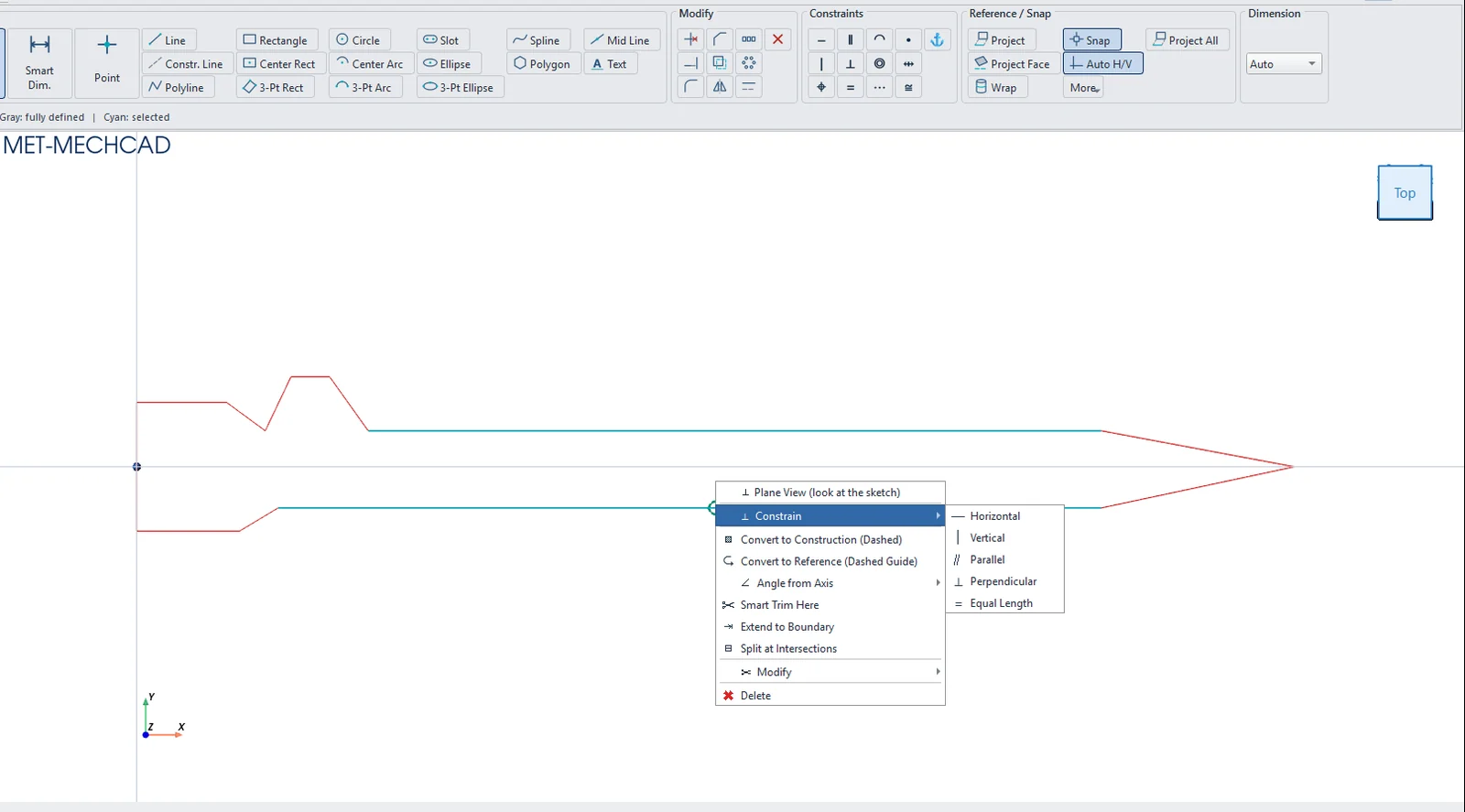
- select the figures first ) - Right-click a line › Constrain (shows only the constraints that fit the selected objects)
Steps
- In Select mode, click the objects (Ctrl+click to select several, or drag a box).
- Click the constraint button you want.
- If you selected the wrong type of object, you see Invalid selection for ….
| Constraint | What to select | Result |
|---|---|---|
| Horizontal / Vertical | One or more lines, or 2 points | Makes them horizontal / vertical |
| Coincident | 2 points or 2 lines | Points coincide (2 lines: joins the nearest ends) |
| Parallel | 2 lines | Parallel to each other |
| Perpendicular | 2 lines | Perpendicular to each other |
| Equal | 2 lines | Equal length |
| Tangent | Line + circle, or 2 circles | Tangent to each other |
| Concentric | 2 circles | Share the same center |
| Equal Radius | 2 circles | Equal radius |
| Midpoint | Point + line | The point is at the midpoint of the line |
| Point On | Point + line or circle | The point lies on the object |
| Symmetric | 2 points + line | Symmetric about the line |
| Fix / Unfix (⚓) | Point | Fixes / releases the position |
Automatic constraints
- Auto H/V (Reference / Snap group): lines that are nearly horizontal/vertical get H/V automatically (the default is set in System Options › Sketching).
- End points placed on a snap get Coincident automatically.
Note: Use the line colors to see whether the sketch is fully defined: red = size not set, yellow = size set but can still move, grey = Fully defined.
Try it: Tent peg
A tent peg has to be perfectly symmetric, otherwise it twists when you hammer it into hard ground. Draw it roughly, then let the constraints straighten it out.
- Click Sketch and press Enter (XY-Plane). Draw a Constr. Line from the origin to about (190, 0). This is the centre line.
- With Line, click around the outline near these points and finish on the first point: (0, −10) → (16, −10) → (22, −6) → (150, −6) → (180, 0) → (150, 6) → (36, 6) → (30, 14) → (24, 14) → (20, 5) → (14, 10) → (0, 10). It does not need to be exact.
- Select the long bottom shaft edge and click Horizontal. Then select both long shaft edges and click Parallel.
- Ctrl+click the two shaft corners near (150, 6) and (150, −6) and the centre line, then click Symmetric.
- Select the tip point and the centre line and click Point On. Select the two short tip edges and click Equal.
- Add Smart Dimensions: 180 from the left edge to the tip, 12 between the two shaft edges and 30 for the tip length (horizontal).
- Click Finish Sketch and Extrude the peg 4 mm.
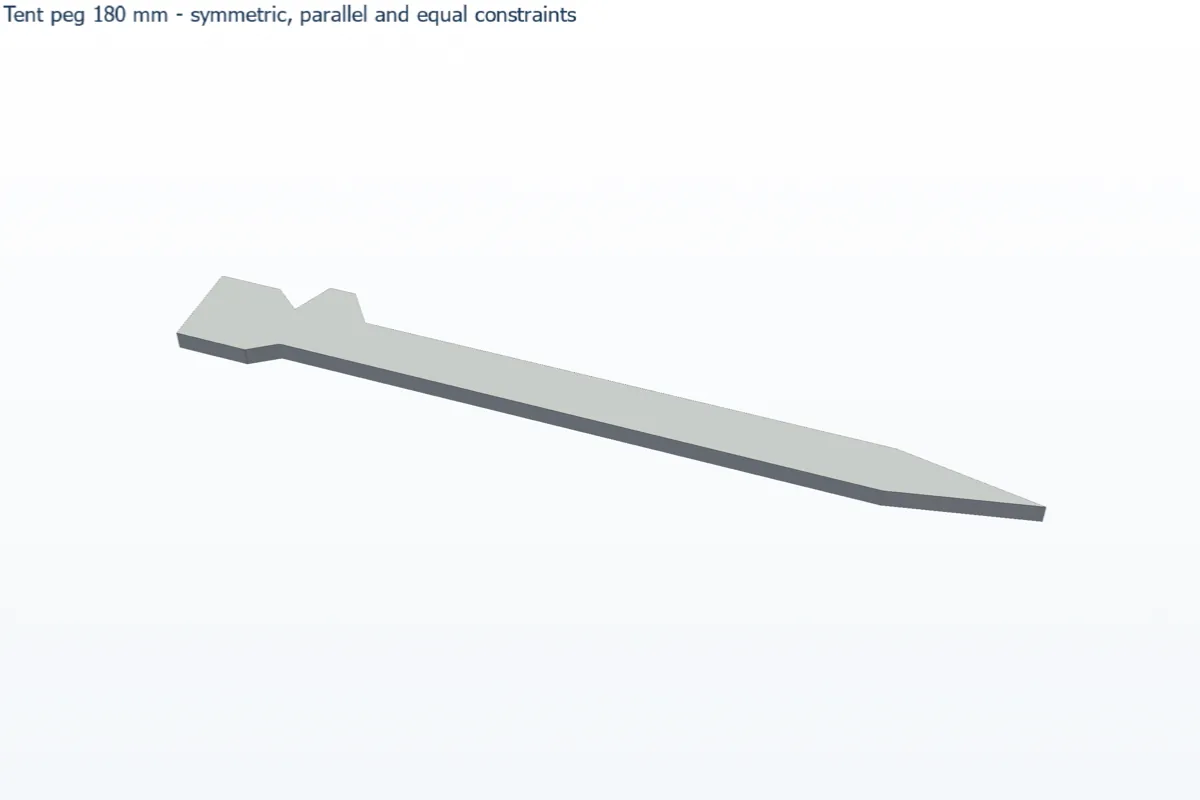
Challenge: Change the shaft width from 12 to 10. The peg stays centred on the centre line and the tip stays sharp, because Symmetric and Point On hold it.