
What it does
Chooses how the part is displayed and adjusts the lighting and background of the 3D view.
Where to find it
- The 4 buttons at the far right of the top bar (available in every workbench)
- View › Display Mode
- The Display panel in Assembly: View & Inspect › View › Display, or the Display (mode, light, shadow) section of the Properties / Info panel
| Mode | Example |
|---|---|
| Shaded | 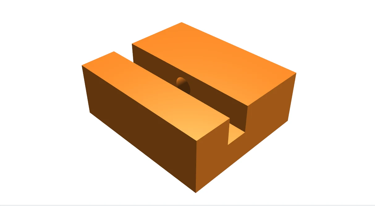 |
| Shaded + Edges (default) | 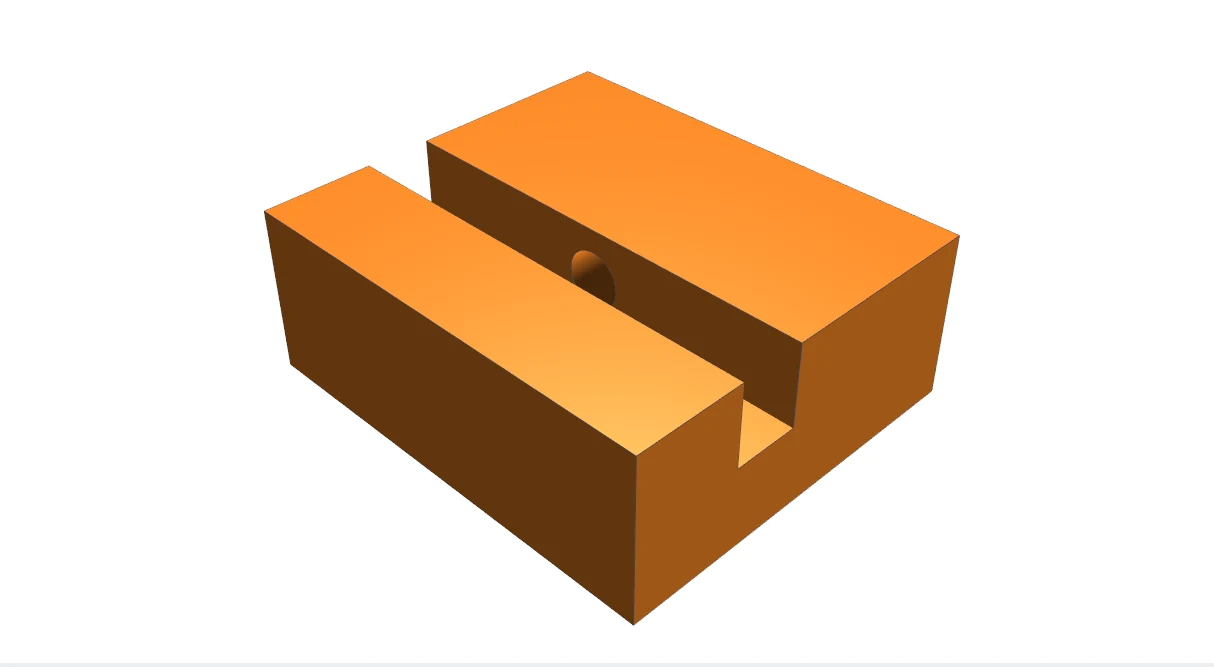 |
| Hidden edges (see-through) | 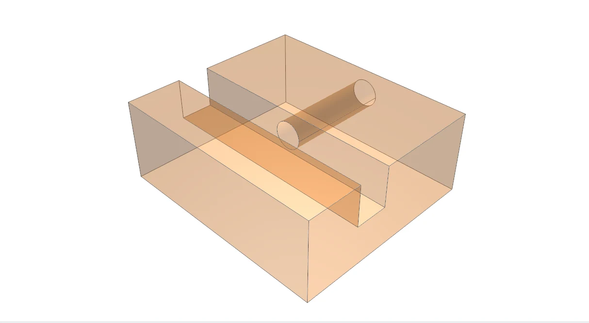 |
| Wireframe | 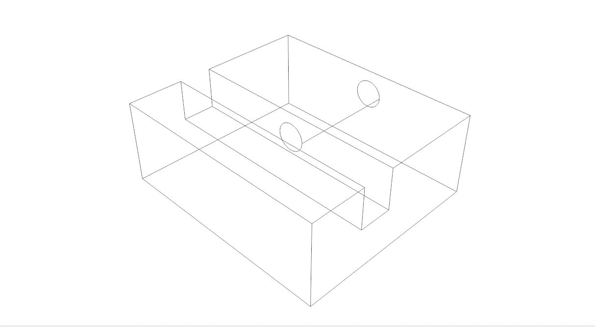 |
Note: In Part Design the Wireframe button shows the same see-through view as Hidden edges; the line-only Wireframe is available in Assembly (the examples above were taken on the Assembly tab).
Display panel
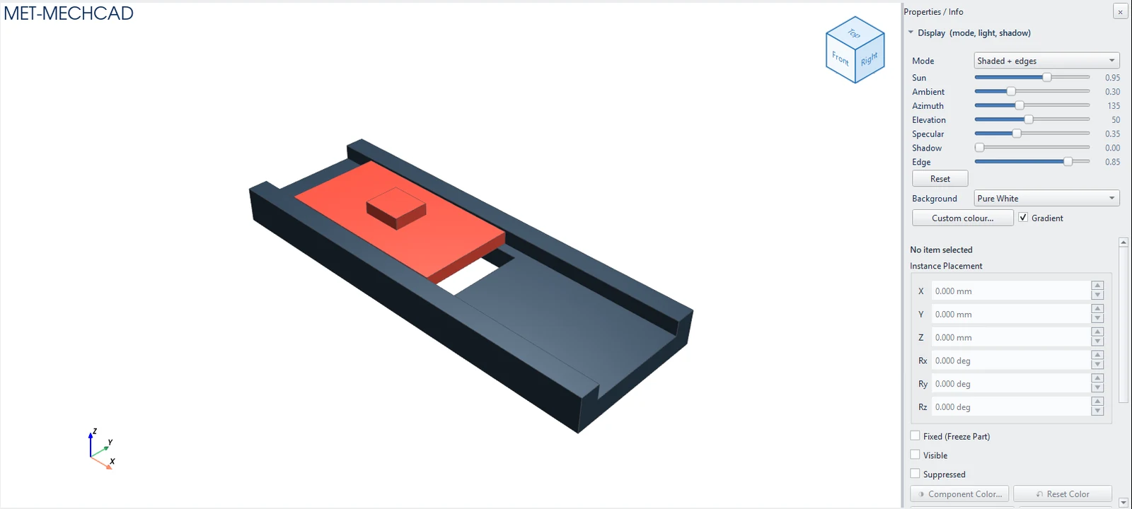
| Option | Range | Default | Description |
|---|---|---|---|
| Mode | – | Shaded + edges | Display mode |
| Sun | 0–1.5 | 0.95 | Brightness of the main light |
| Ambient | 0–1 | 0.30 | Ambient light |
| Azimuth | 0–360 | 135 | Horizontal light direction |
| Elevation | 15–90 | 50 | Light elevation angle |
| Specular | 0–1 | 0.35 | Glossiness |
| Shadow | 0–0.8 | 0 | Strength of the shadow on the floor |
| Edge | 0.1–1 | 0.85 | Edge line strength |
| Reset | Restores lighting, shadow and edges (keeps the mode) | ||
| Background | Pure White | Pure White, Light, Dark, Blueprint, Studio and the classic style | |
| Custom colour… / Gradient | Your own background colour and gradient |
Note: Assemblies with many parts (more than about 1,500) turn shadows off automatically for speed: Shadow is off for large assemblies.
Try it: Slot phone stand with a hidden cable channel
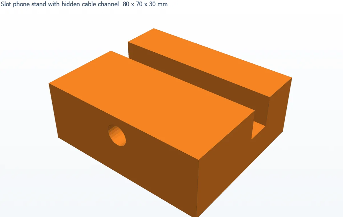
A solid block with a slot holds your phone upright, and a tunnel at the back lets the charging cable reach it. The tunnel is hidden inside the part, which makes this the perfect model for trying all four display modes.
- Sketch on XY: press R, click the origin, type 80, Tab, 70, Enter. Finish Sketch and Extrude 30 mm.
- Right-click the top face › New Sketch on this face. Draw a rectangle 80 × 12 right across the part, 20 mm from the front edge (use D for the 20). Finish Sketch, then Cut / Remove › Extrude with Depth 15.
- Right-click the back face (80 × 30) › New Sketch on this face. Draw a Ø10 circle, 40 mm from the side and 9 mm below the top edge. Finish Sketch, then cut it with Depth 38, so it stops exactly in the slot.
- Click the four display buttons at the right of the top bar one by one:
- Shaded: you see only a hole in the back.
- Hidden edges: the tunnel now shows through the block all the way to the slot.
- Wireframe: every edge, including the round channel.
- Shaded + Edges: back to the normal working view.
Challenge: Your phone has a thick case? Edit the slot sketch to 14 mm and check the result in Hidden edges.