
What it does
The menu bar collects the commands for files, import/export, settings and licence. The menu commands are the same as the buttons on the ribbon.
File
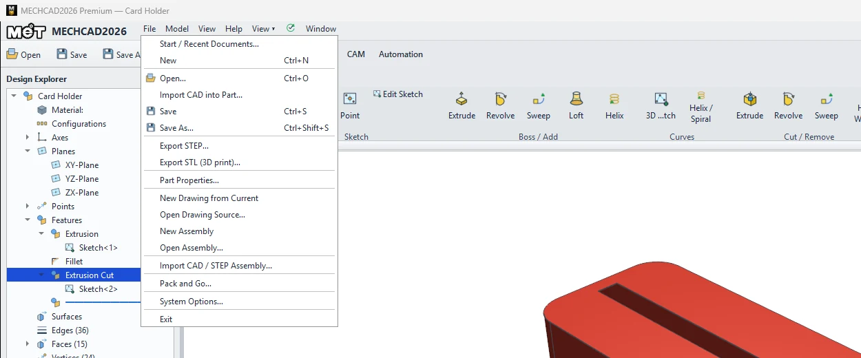
| Command | Shortcut | Meaning |
|---|---|---|
| Start / Recent Documents… | Opens the Start Center | |
| New | Ctrl+N | New document for the active tab |
| Open… | Ctrl+O | Opens a MECHCAD file or another CAD file |
| Import CAD into Part... | Imports STEP/IGES/X_T/SolidWorks/Alibre as a part. See Import CAD | |
| Save / Save As… | Ctrl+S / Ctrl+Shift+S | Saves the document on screen |
| Export STEP… / Export STL (3D print)… | Exports the part. See Export STEP / STL | |
| Part Properties… | Part data for the title block and BOM | |
| New Drawing from Current / Open Drawing Source… | Creates a drawing from a part/assembly | |
| New Assembly / Open Assembly… | Opens an Assembly tab | |
| Import CAD / STEP Assembly... | Imports an assembly | |
| Pack and Go… | Bundles an assembly and its components into one file. See Pack and Go | |
| System Options… | Program settings. See System Options | |
| Exit | Exits the program |
Model
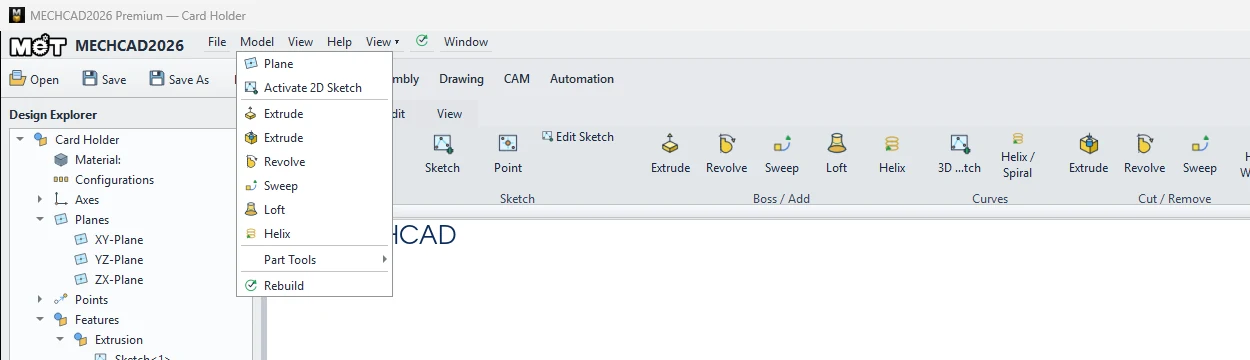
The main part-building commands: Plane, Activate 2D Sketch, Extrude (Boss/Cut), Revolve, Sweep, Loft, Helix, the Part Tools submenu (Fillet, Chamfer, Shell, Hole Wizard, Mirror, Pattern, Part Color, Union/Subtract/Intersect/Scale) and Rebuild.
View
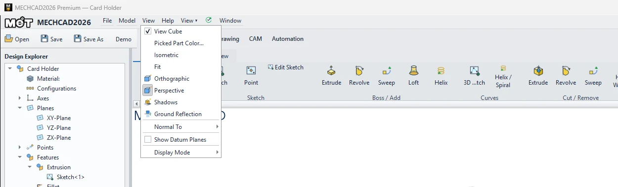
| Command | Meaning |
|---|---|
| View Cube | Shows/hides the View Cube |
| Picked Part Color… | The color used to highlight the selected component (default blue) |
| Isometric / Fit | Isometric view / zoom to fit |
| Orthographic / Perspective | Projection type |
| Shadows / Ground Reflection | Shadows and ground reflection |
| Normal To › XY / YZ / ZX | Looks perpendicular to the plane |
| Show Datum Planes | Shows the reference planes (Ctrl+Shift+P) |
| Display Mode | Shaded / Shaded + Edges / Hidden Edges |
Help
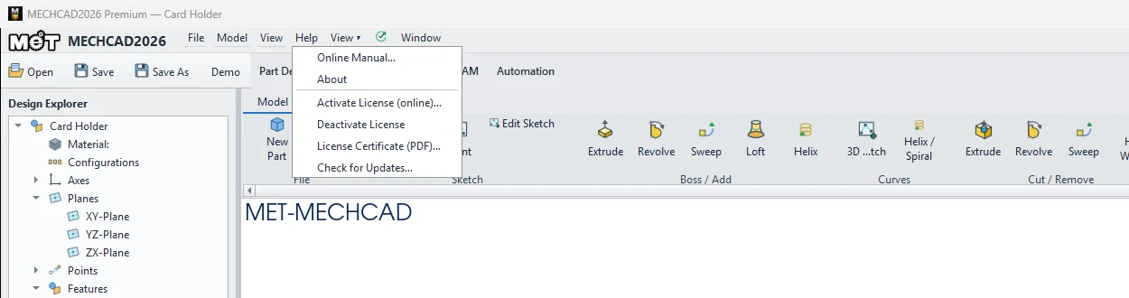
| Command | Meaning |
|---|---|
| Online Manual… | Opens the online manual |
| About | Version information |
| Activate License (online)… | Opens the Welcome window / enter a license key |
| Deactivate License | Releases this computer's seat to the server (before moving to another computer) |
| License Certificate (PDF)… | Creates a licence certificate as a PDF |
| Check for Updates… | Checks for a new version (MA customers) |
Try it: Business-card holder using only the menu bar
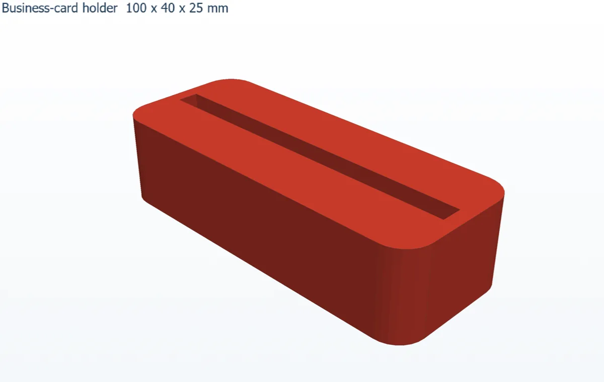
Make a stand that keeps your business cards upright on the desk, and use the menus at the top for every main step, from New to the STL file.
- Choose File › New on the Part Design tab.
- Choose Model › Activate 2D Sketch, pick XY, and draw a rectangle 100 × 40 from the origin. Click Finish Sketch.
- Choose Model › Extrude (Boss) with Depth 25.
- Choose Model › Part Tools › Fillet, set Radius 8 and click the four vertical corner edges, then Done.
- Right-click the top face › New Sketch on this face. Draw a rectangle 92 × 6, 4 mm from the left edge and 17 mm from the front edge. Finish Sketch, then choose Model › Extrude (Cut) with Depth 18. A standard 90 × 55 mm card stands in the slot with its top sticking out.
- Choose File › Part Properties… and enter the description Business card holder.
- Choose File › Export STL (3D print)… and save
card-holder.stl.
Challenge: Use View › Normal To › XY to look straight down and check that the slot is centred.