
What it does
Imports CAD files from other programs into MECHCAD.
Where to find it
| Command | Result |
|---|---|
| File › Open… | Opens a CAD file in a new tab according to its type. |
| File › Import CAD into Part... | Opens it in Part Design. Simple parts that pass validation become editable features (Import CAD into Part Design window). |
| File › Import CAD / STEP Assembly... | Imports an assembly as parts with their positions (Import CAD window). |
| Assembly › Insert Part | Inserts a CAD file into the open assembly. |
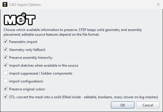
CAD Import Options
| Option | Default | Description |
|---|---|---|
| Parametric import | On | Creates editable features when the source data has them. |
| Geometry-only fallback | On | If features cannot be created, imports a solid. |
| Preserve assembly hierarchy | On | Keeps the sub-assembly structure. |
| Import sketches when available in the source | On | Imports sketches when they exist. |
| Import suppressed / hidden components | Off | Imports hidden/suppressed parts. |
| Import configurations | Off | Imports configurations. |
| Preserve original colors | On | Keeps the original colours. |
| STL: convert the mesh into a solid | On (STL only) | Converts the mesh to a solid (allows Boolean edits and mass calculation, but is slow for large meshes). |
At least one of the first two options must be on (Enable Parametric import or Geometry-only fallback.).
Steps
- Choose an import command, then choose the file.
- Set the options in the CAD Import Options window, then click OK.
- Wait for the progress bar (Reading CAD product structure…, Meshing part n / total). Click Cancel to cancel.
- When it finishes, a report shows Native parametric import / Neutral assembly import / Geometry-only import with the number of parts.
Note: A part imported without history can be edited with Move Face, or converted to features with Recognize Features. An imported part that is tilted can be straightened with Auto Align in Assembly.
Try it: Under-desk holder for a USB hub
Many manufacturers publish STEP models of their products. Import one, measure it, and design a holder that clips the hub under your desk.
- No STEP file at hand? Make a stand-in: a new part, rectangle 100 × 30, Extrude 12, then File › Export STEP… as
usb-hub.step. Close the part. - Choose File › Import CAD into Part... and pick the STEP file. Keep the default CAD Import Options and click OK. The report tells you which kind of import was used.
- Right-click in the view › Size Box: 100 × 30 × 12 mm. Plan for 0.5 mm of clearance on every side.
- New part: rectangle 80 × 40, Extrude 18. Right-click an end face (40 × 18) › New Sketch on this face: rectangle 31 × 13, 4.5 mm from the side and 3 mm from the bottom. Cut it Through All: this is the tunnel for the hub.
- Right-click the top face › New Sketch on this face. Draw two 40 × 15 tabs, one along each long edge, outside the body. Extrude 5 mm with ⇄ so they grow downward and stay flush with the top.
- Sketch a Ø4.5 hole in the middle of each tab and cut Through All. Screw the holder under the desk and slide the hub in.
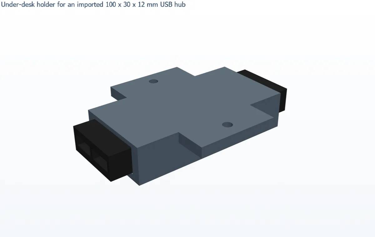
Challenge: Import the hub with File › Import CAD / STEP Assembly... instead, and place it in the holder in the Assembly tab to check the fit.