
What it does
A single click on an operation in the CAM Manager only selects it. Double-click it (or right-click › Edit Parameters) to open the operation box under the CAM Manager and show its toolpath. The box is split into collapsible sections. Fields that do not apply to that operation are not shown.
| Section in the box | Description |
|---|---|
| Features | Input type, the Add / Done / Remove / Reverse / Open/Close buttons for the picked edges/faces, Pick, Toolpath side |
| Tool | Tool selector (grouped by tool type, with a filter box) and Speed S / Feed F |
| Depths | Top Z, Bottom Z, Stepdown |
| Strategy and steps | Pocket pattern, Stepover, Cuts, Moves outside the stock as rapids |
| Path Setting | Tool Compensation and D register (Profile, Ramp Cut, Chamfer, Corner Round), and Chamfer width / Tip offset (Chamfer) |
| Lead in / Lead out | How the tool enters and leaves the cut |
| Limiting: Check surfaces | Surfaces the tool must not cut (Pick surfaces / Clear buttons) |
| Holes | The Smart Hole table of a drilling operation (see Drill and Hole) |
| Parameters | All the pages in the table below |
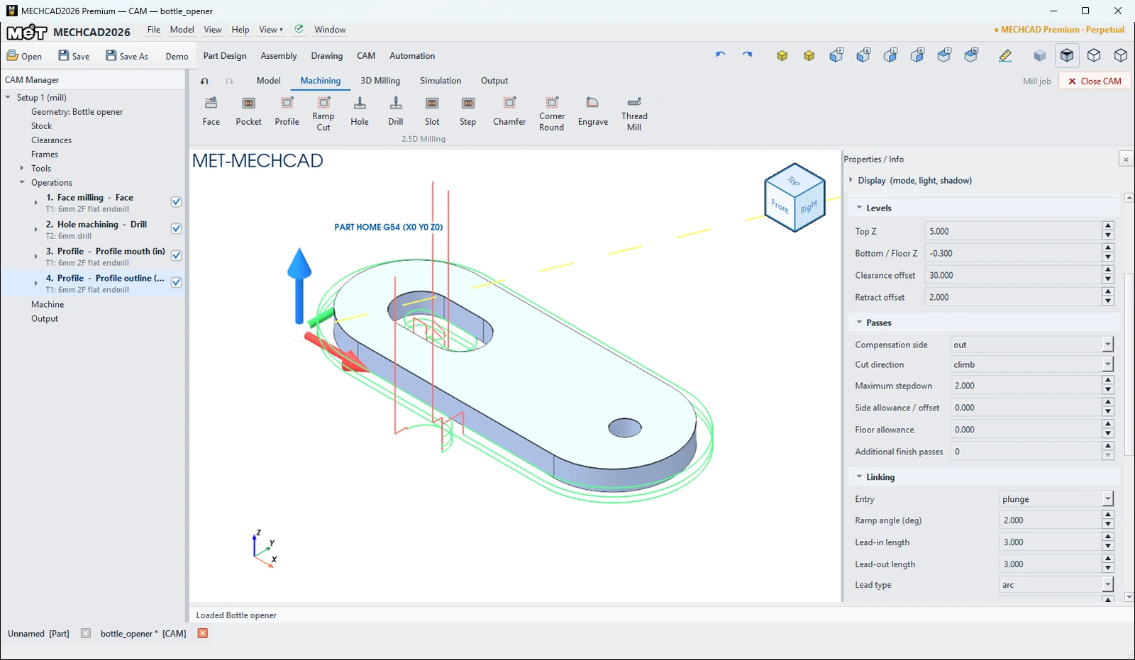
| Section | Key fields |
|---|---|
| General | Operation name, Suppress operation, Tolerance (mm) 0.01 |
| Geometry | Source (model / faces / sketch / feature / profile), Edge chain, buttons Select Faces / Select Sketch/Chain / Select Feature |
| Tool | Cutter / insert, Spindle RPM (0=tool), Cut feed mm/min (0=tool), Plunge feed (0=tool), Coolant, Feed mode, CSS, Maximum RPM |
| Levels | Top Z, Bottom / Floor Z, Depth, Clearance offset (5), Retract offset (2) |
| Passes | Cutting tactic (zigzag / concentric), Compensation side (out / in / on), Cut direction (climb / conventional / both), Stepover, Maximum stepdown, Stock to leave, Finish allowance, Peck depth |
| Linking | Entry (plunge / ramp / helix / outside), Ramp angle 2°, Lead-in / Lead-out length, Lead type (arc / line / none), Tool Compensation (None / Computer, Offset (G41/G42 on contour), Wear (G41/G42 on centre path)), D register (0=tool no.), Output arcs (G2/G3), Transfer mode, Skip air cuts |
| Stock | Input stock (ignore / previous / reference), Reference operation, Publish result to downstream ops |
| Turning | Cut region (OD / ID / face / profile / axial), NC cycle output, Longitudinal direction, Thread infeed, Thread / Spring passes |
Tool Compensation (D-offset)
| Value | Description |
|---|---|
| None / Computer | MECHCAD compensates the cutter radius; the NC follows the cutter-centre path with no G41/G42 (default). |
| Offset (G41/G42 on contour) | The NC follows the part contour, with G41/G42 + D on the lead-in and G40 on the lead-out. The control offsets by the radius in D. |
| Wear (G41/G42 on centre path) | The NC follows the cutter-centre path, plus G41/G42 + D. D holds only the wear. |
| D register (0=tool no.) | The D number output with G41/G42. 0 = the tool's D offset (Speeds tab of the Tool box), or the tool number. |
See Profile and Ramp Cut for details and an example.
Right-click menu on an operation
| Menu | Description |
|---|---|
| Edit Parameters | Opens the operation box. |
| Simulate this operation | Simulates this operation only. |
| Recalculate | Recalculates the toolpath. |
| Duplicate | Copies the operation ( |
| Move Up / Move Down | Changes the operation order (Alt+Up / Alt+Down, or drag and drop). |
| Change type... | Changes the operation type and keeps the picked edges/faces, tool, depths and leads. |
| Change Tool › | Changes the tool. |
| Rest machining from › | (3D) Cuts only the material left by a previous operation. |
| Show / Hide Toolpath, Hide All Toolpaths | Shows or hides toolpaths. |
| Delete | Deletes the operation (asks for confirmation). |
Note: Clear the tick box in front of an operation to suppress it (its name then starts with [Suppressed]). Under each operation, the sub-rows Tool:, Geometry:, Tactic:, Levels:, Cutting: and Linking: jump straight to that section when you click them.
Try it: Tune the pocket of a coin tray
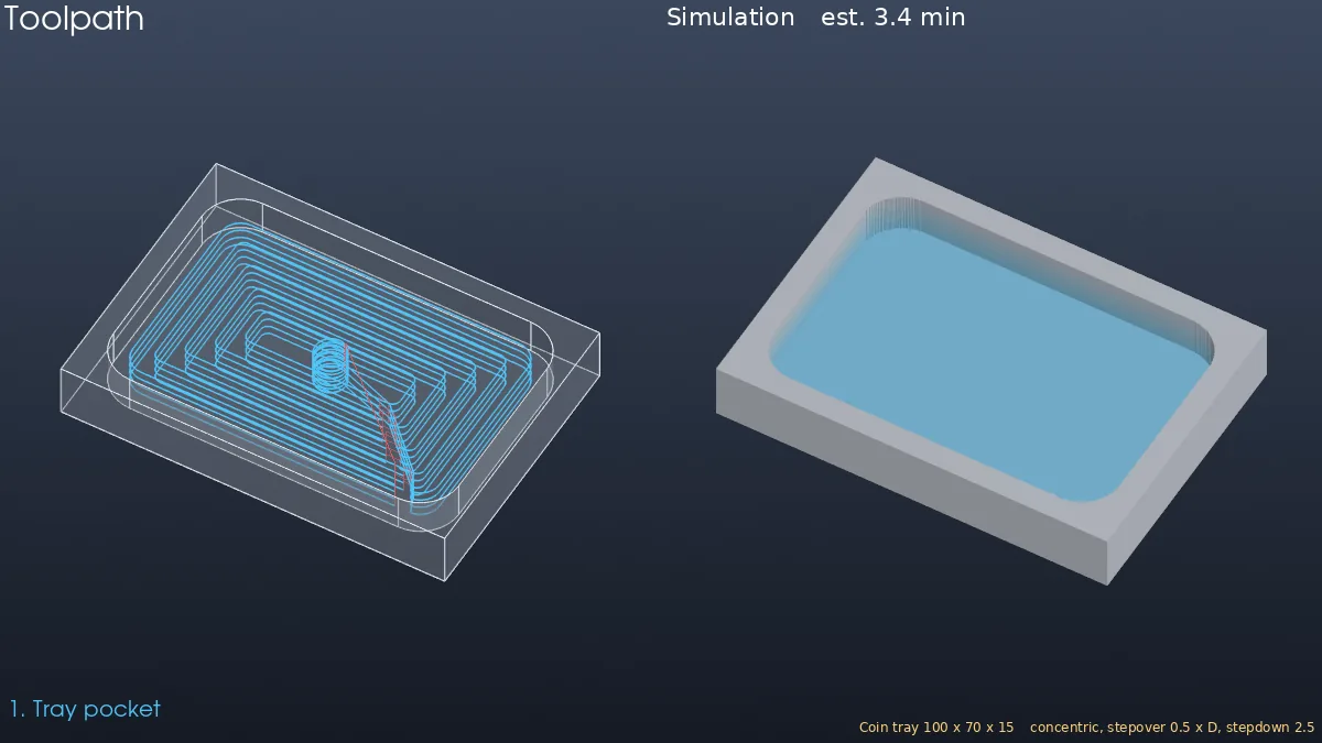
A 100 × 70 × 15 desk tray for coins and keys. You make one Pocket, then tune it field by field in the operation box.
- Model a 100 × 70 block Extruded 15 mm. On the top face, sketch a 90 × 60 rectangle 5 mm in from every edge, with R10 corners, and Extrude Cut it 10 mm.
- CAM › New Job › Mill Template. Click Pocket, click the tray floor and press Enter.
- Double-click the operation in the CAM Manager. On the General page of the Parameters section, set Operation name to
Tray pocket. - In Tool, set Cutter / insert to T13 (10 mm), Spindle RPM to 4000 and Cut feed to 1200.
- In Passes, set Cutting tactic to
concentric, Stepover to 0.5, Maximum stepdown to 2.5 and Corner smoothing radius to 2. - In Linking, keep Entry
helixand set Ramp angle to 3. - Right-click the operation › Recalculate, then Simulate. The estimated time is about 3.4 min, and the G-code shows
T13,S4000and a helical G03 entry at F1200.
Challenge: Right-click › Duplicate, clear the tick of the original to suppress it, and set the copy back to zigzag. Which tactic is faster for this tray?
Note: CAM is available only in MECHCAD Premium (and during the trial).