
What it does
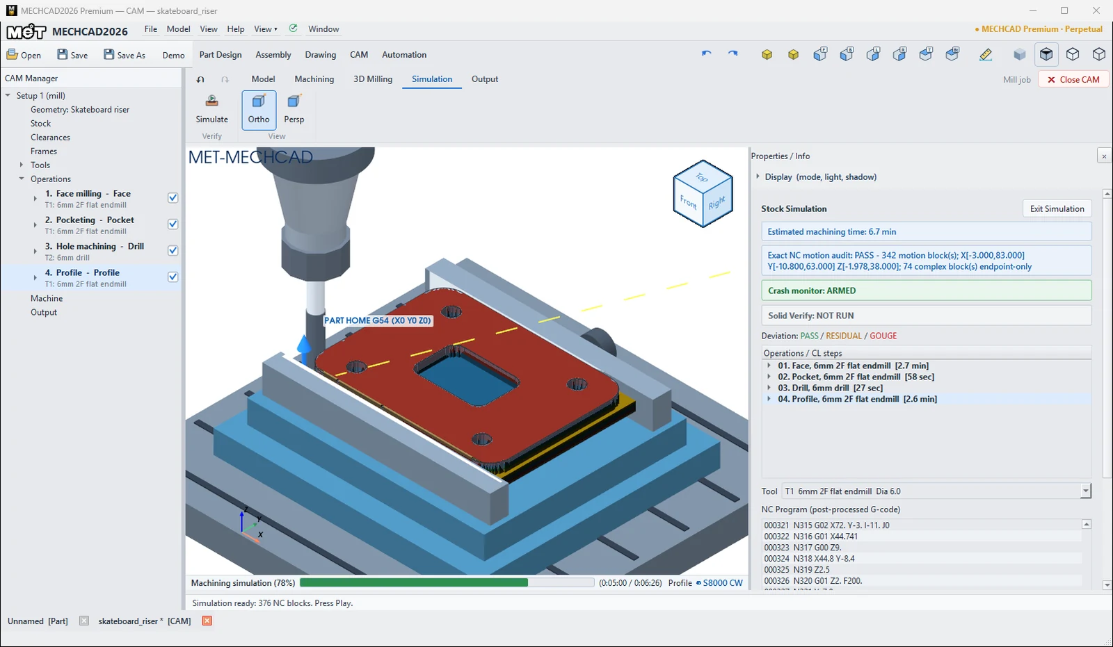
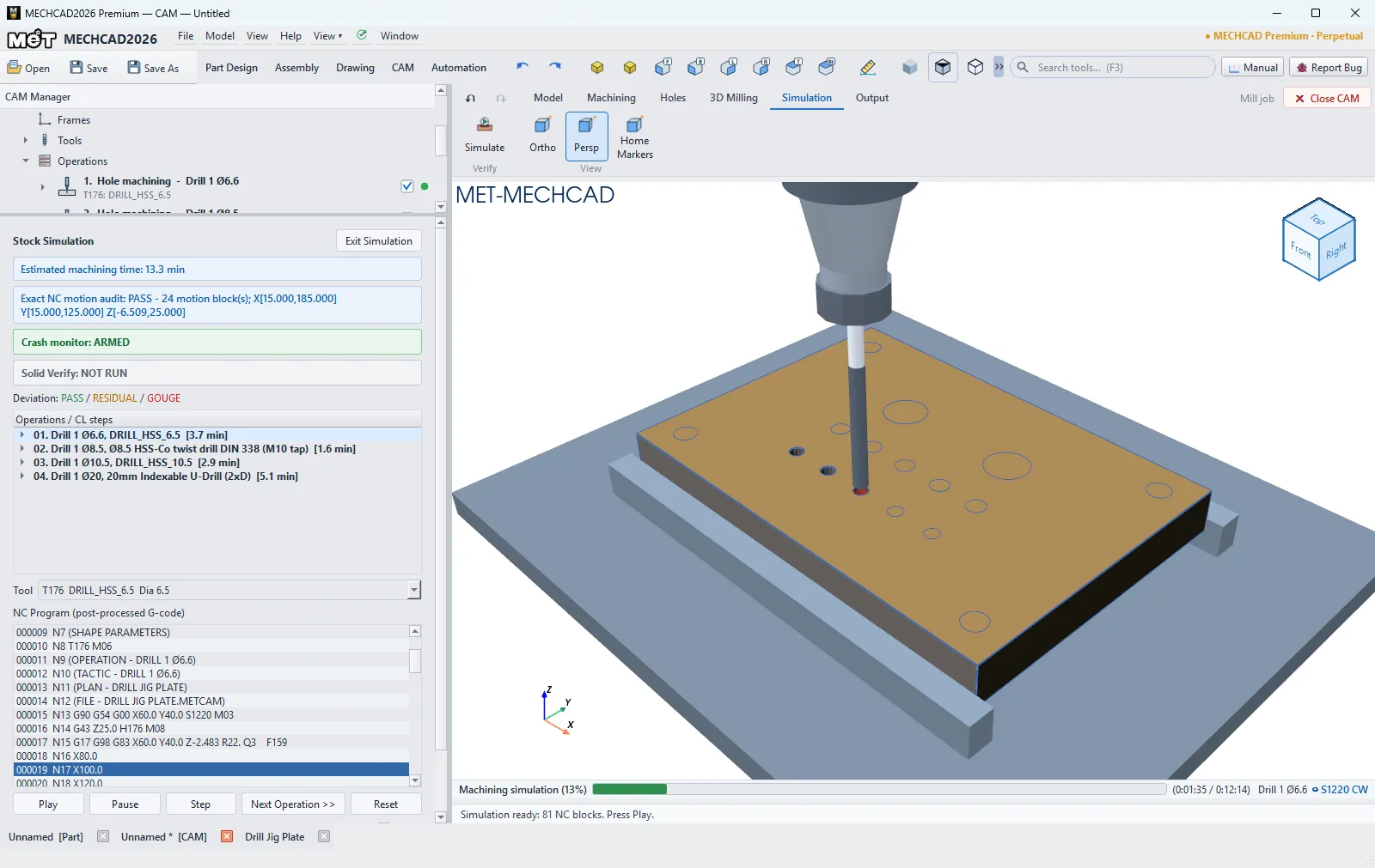
Simulates material removal on the raw stock using the post-processed G-code. It checks the cutter and holder for collisions with the vise/chuck, and checks the surface result (Solid Verify).
Where to find it
Simulation › Verify › Simulate (and Output › Simulate)
Steps
- Click Simulate. The program checks the setup first. If there are errors, Setup errors — … blocked opens and you must fix them first (warnings ask Continue anyway?).
- Wait for Preparing toolpaths... until Simulation ready: N NC blocks. Press Play. appears.
- Click Play / Pause / Step / Next Operation >> / Reset. Adjust Speed and Loop.
- After playback, check the Solid Verify result (PASS / RESIDUAL / GOUGE).
- Click Exit Simulation to go back to editing.
| Item | Description |
|---|---|
| Estimated machining time | Estimated cutting time |
| Exact NC motion audit | Checks the G-code motion against the travel limits |
| Crash monitor: ARMED | Checks for collisions. If one occurs, it stops with CRASH ALARM before the crash. |
| Solid Verify / Deviation | PASS / RESIDUAL (material left) / GOUGE (overcut) |
| Operations / CL steps | Double-click to jump to a step. |
| Tool | Changes the tool of the selected operation. |
| NC Program (post-processed G-code) | The current line is highlighted. |
| Part ghost / Stock transparent / Tool holder / Vise / Chuck | Display options |
| Status bar | Machining simulation (NN%), time, operation, spindle speed |
Cutter shape in the simulation
The cutter in the simulation is drawn from the actual tool, and material is removed with the same shape, so the result matches the tool geometry.
| Tool type | Simulated tip |
|---|---|
| Ball | Half sphere |
| Bull nose (with a Corner radius) | Flat with rounded corners of that radius |
| Chamfer, Engraver | A cone of the Included angle, with a flat tip of the Tip diameter |
| Drill, Spot/Center | A point of the drill's point angle (for example 118°); an angle of 0 gives a flat-bottom drill |
| Corner round | A concave rounded tip of that radius |
| Other tools (Flat) | Flat |
When you edit a tool (for example the angle or tip of a chamfer mill, a corner radius, the diameter or the type), the cutter is redrawn at once, the toolpaths that use the tool are marked for recalculation, and the next simulation uses the new shape.
Note: The setup check covers, for example: a missing tool or a tool value of 0, holes with no position, a floor above the top surface, cutting into the table, a depth greater than the flute length, a stepdown of 0, threads and grooves in the wrong order, a post that does not match the machine type, and a WCS that is not G54–G59.
Try it: Watch a skateboard riser being cut
An 80 × 60 × 8 aluminium riser pad with four truck holes (54 × 41 pattern) and a lightening pocket. You build four operations, then use the simulator to check each one before you trust the G-code.
- Model an 80 × 60 plate with R8 corners, Extruded 8 mm. Add four Ø6 holes at X 13 / 67 and Y 9.5 / 50.5, Through All. Add a 30 × 20 pocket with R4 corners in the centre, 4 mm deep.
- CAM › New Job › Mill Template. In Stock, choose Part + allowance (0.5 mm on top to face) and set Support height (parallels) to 3. Add a Face (top), a Pocket (pocket floor), a Drill (four hole walls, Depth 10) and a Profile (top outer edge, Bottom / Floor Z −0.3).
- Click Simulate and wait for Simulation ready: N NC blocks. Press Play.
- Click Play and drag Speed. Use Next Operation >> to jump from one operation to the next. Click Pause during the Profile: the current line is highlighted in NC Program.
- Turn on Stock transparent or Tool holder to look at the cutter from any side.
- After playback, read Solid Verify. The check compares on a grid (about 0.6 mm on this part), so a few single cells exactly on a vertical wall can be flagged. A real problem shows up as a coloured patch.
- Click Exit Simulation to go back to editing.
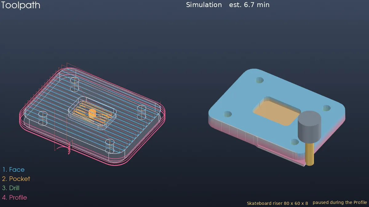
Challenge: Set the pocket's Maximum stepdown to 4 (one level only), simulate again and compare the estimated time with the 6.7 min you had before.
Note: CAM is available only in MECHCAD Premium (and during the trial).